Nissan Juke F15. Manual - part 400
P0524 ENGINE OIL PRESSURE
EC-413
< DTC/CIRCUIT DIAGNOSIS >
[MR FOR NISMO RS MODELS]
C
D
E
F
G
H
I
J
K
L
M
A
EC
N
P
O
1. Turn ignition switch ON.
2. Select “DATA MONITOR” mode of “ENGINE” using CONSULT.
3. Start the engine and check that “EOP SENSOR” changes, according to engine speeds.
Without CONSULT
Check engine oil level. Refer to
.
Is the inspection result normal?
YES
>> GO TO 3.
NO
>> Proceed to
.
Diagnosis Procedure
INFOID:0000000012197952
1.
CHECK ENGINE OIL LEVEL
1. Turn ignition switch OFF.
2. Check engine oil level. Refer to
.
Is the inspection result normal?
YES
>> GO TO 2.
NO
>> GO TO 4.
2.
CHECK ENGINE OIL PRESSURE
With CONSULT
1. Turn ignition switch ON.
2. Select “DATA MONITOR” mode of “ENGINE” using CONSULT.
3. Start the engine and check that “EOP SENSOR” changes, according to engine speeds.
Without CONSULT
Check engine oil pressure. Refer to
.
Is the inspection result normal?
YES
>> GO TO 3.
NO
>> Check oil pump. Refer to
3.
CHECK EOP SENSOR
Check EOP sensor. Refer to
EC-414, "Component Inspection"
Is the inspection result normal?
YES
>> Check intermittent incident. Refer to
GI-45, "Intermittent Incident"
.
NO
>> Repair or replace error-detected parts.
4.
CHECK ENGINE OIL LEAKAGE
Check engine oil leakage. Refer to
LU-8, "Engine Lubrication System"
.
Is the inspection result normal?
YES
>> GO TO 5.
NO
>> Repair or replace error-detected parts.
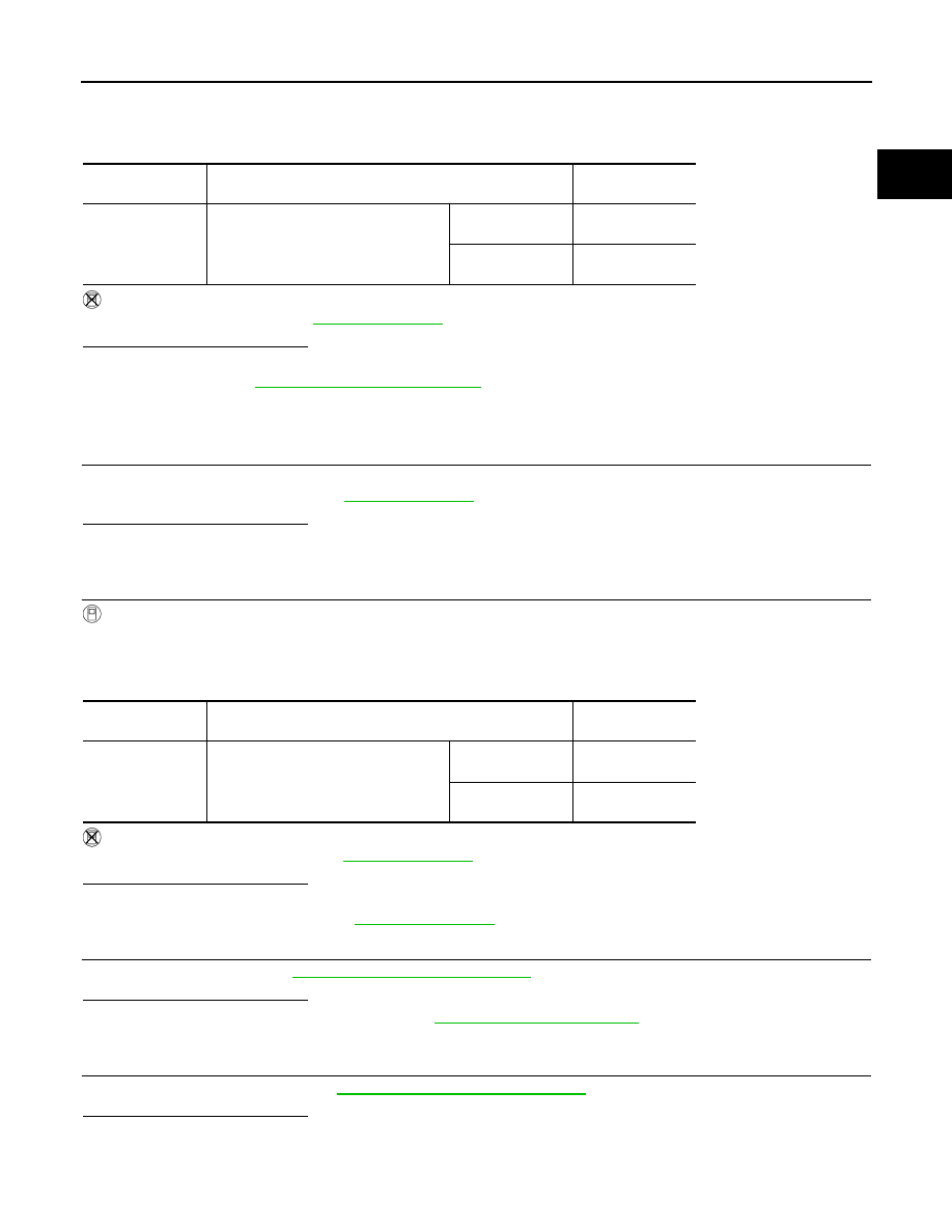
Monitor item
Condition
Value
(Approx.)
EOP SENSOR
• Engine oil temperature: 80
°C (176°F)
• Selector lever: P or N position
• Air conditioner switch: OFF
• No load
Engine speed:
Idle
1,450 mV or more
Engine speed:
2,000 rpm
2,850 mV or more
Monitor item
Condition
Value
(Approx.)
EOP SENSOR
• Engine oil temperature: 80
°C (176°F)
• Selector lever: P or N position
• Air conditioner switch: OFF
• No load
Engine speed:
Idle
1,450 mV or more
Engine speed:
2,000 rpm
2,850 mV or more