Nissan Juke F15. Manual - part 363
P0130 A/F SENSOR 1
EC-265
< DTC/CIRCUIT DIAGNOSIS >
[MR FOR NISMO RS MODELS]
C
D
E
F
G
H
I
J
K
L
M
A
EC
N
P
O
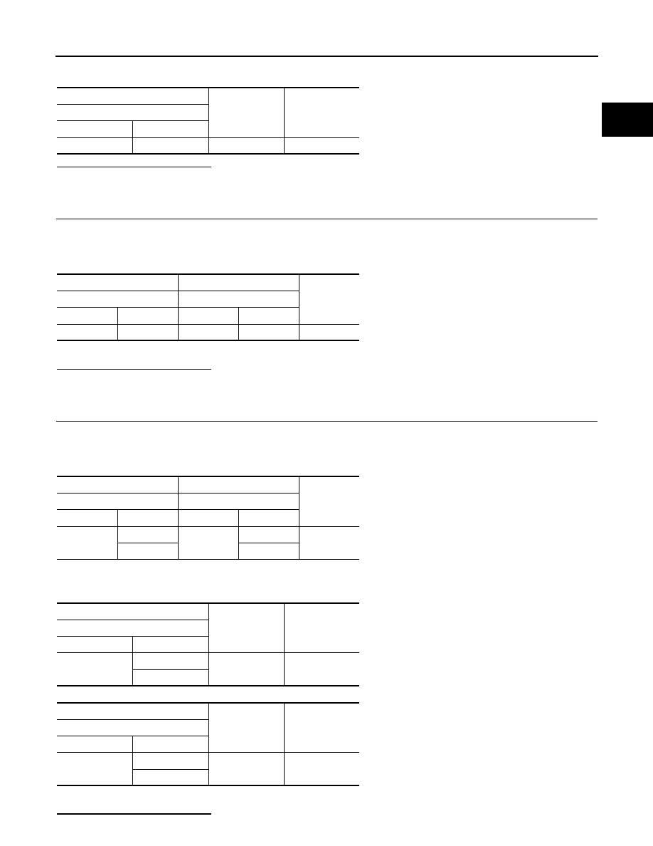
4. Check the voltage between A/F sensor 1 harness connector and ground.
Is the inspection result normal?
YES
>> GO TO 3.
NO
>> GO TO 2.
2.
CHECK AIR FUEL RATIO (A/F) SENSOR 1 POWER SUPPLY CIRCUIT
1. Turn ignition switch OFF.
2. Disconnect IPDM E/R harness connector.
3. Check the continuity between A/F sensor 1 harness connector and IPDM E/R harness connector.
4. Also check harness for short to ground.
Is the inspection result normal?
YES
>> Perform the trouble diagnosis for power supply circuit.
NO
>> Repair or replace error-detected parts.
3.
CHECK A/F SENSOR 1 INPUT SIGNAL CIRCUIT
1. Turn ignition switch OFF.
2. Disconnect ECM harness connector.
3. Check the continuity between A/F sensor 1 harness connector and ECM harness connector.
4. Check the continuity between A/F sensor 1 harness connector and ground, or ECM harness connector
and ground.
5. Also check harness for short to power.
Is the inspection result normal?
+
−
Voltage
A/F sensor 1
Connector
Terminal
F70
4
Ground
Battery voltage
+
−
Continuity
A/F sensor 1
IPDM E/R
Connector
Terminal
Connector
Terminal
F70
4
E14
36
Existed
+
−
Continuity
A/F sensor 1
ECM
Connector
Terminal
Connector
Terminal
F70
1
F25
21
Existed
2
25
+
−
Continuity
A/F sensor 1
Connector
Terminal
F70
1
Ground
Not existed
2
+
−
Continuity
ECM
Connector
Terminal
F25
21
Ground
Not existed
25