Nissan Juke F15. Manual - part 350


  Index      Nissan     Nissan Juke F15 (2015 year) - Service and Repair Manual


Search            


Content   ..  348  349  350  351   ..


Nissan Juke F15. Manual - part 350


P0075 IVT CONTROL SOLENOID VALVE

EC-213

< DTC/CIRCUIT DIAGNOSIS >

[MR FOR NISMO RS MODELS]

C

D

E

F

G

H

I

J

K

L

M

A

EC

N

P

O

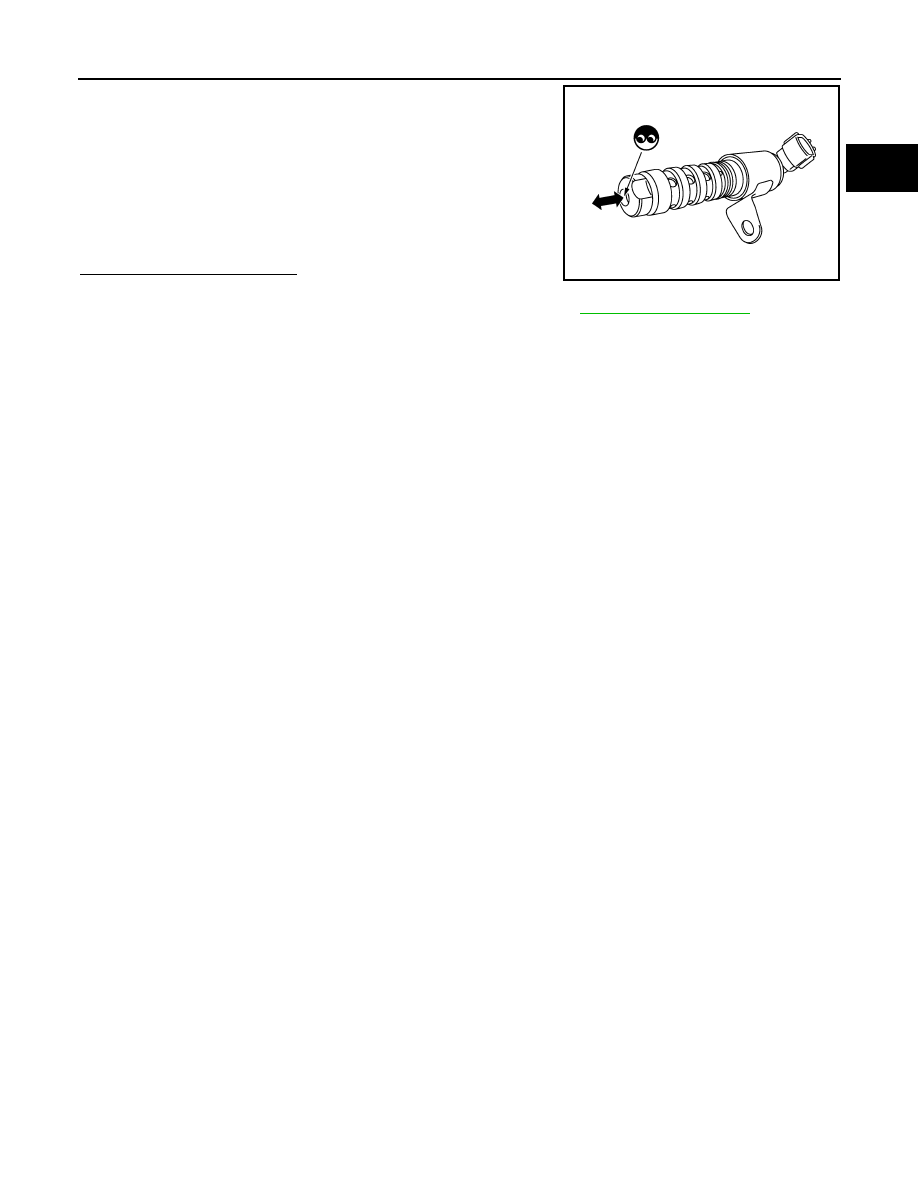
2. Provide 12 V DC between intake valve timing control solenoid

valve terminals 1 and 2, and then interrupt it. Make sure that the

plunger moves as shown in the figure.

CAUTION:

Do not apply 12 V DC continuously for 5 seconds or more.

Doing so may result in damage to the coil in intake valve

timing control solenoid valve.

NOTE:

Always replace O-ring when intake valve timing control

solenoid valve is removed.

Is the inspection result normal?

YES

>> INSPECTION END

NO

>> Replace intake valve timing control solenoid valve. Refer to 

EM-76, "Exploded View"

.

JMBIA2107ZZ

EC-214

< DTC/CIRCUIT DIAGNOSIS >

[MR FOR NISMO RS MODELS]

P0078 EVT CONTROL SOLENOID VALVE

P0078 EVT CONTROL SOLENOID VALVE

DTC Logic

INFOID:0000000012197770

DTC DETECTION LOGIC

DTC CONFIRMATION PROCEDURE

1.

PRECONDITIONING

If DTC Confirmation Procedure has been previously conducted, always perform the following procedure

before conducting the next test.

1. Turn ignition switch OFF and wait at least 10 seconds.

2. Turn ignition switch ON.

3. Turn ignition switch OFF and wait at least 10 seconds.

>> GO TO2.

2.

PERFORM DTC CONFIRMATION PROCEDURE

1. Start engine and let it idle for 5 seconds.

2. Check 1st trip DTC.
Is 1st trip DTC detected?

YES

>> Proceed to 

EC-214, "Diagnosis Procedure"

.

NO

>> INSPECTION END

Diagnosis Procedure

INFOID:0000000012197771

1.

CHECK EXHAUST VALVE TIMING CONTROL SOLENOID VALVE POWER SUPPLY

1. Turn ignition switch OFF.

2. Disconnect exhaust valve timing (EVT) control solenoid valve harness connector.

3. Turn ignition switch ON.

4. Check the voltage between exhaust valve timing control solenoid valve harness connector and ground.

Is the inspection result normal?

YES

>> GO TO 3.

NO

>> GO TO 2.

2.

CHECK EXHAUST VALVE TIMING CONTROL SOLENOID VALVE POWER SUPPLY CIRCUIT

1. Turn ignition switch OFF.

2. Disconnect IPDM E/R harness connector.

3. Check the continuity between EVT control solenoid valve harness connector and IPDM E/R harness con-

nector.

DTC No.

Trouble diagnosis name

(Trouble diagnosis content)

DTC detecting condition

Possible cause

P0078

EX V/T ACT/CIRC-B1
(Exhaust valve timing control sole-
noid valve circuit)

An improper voltage is sent to the ECM 
through exhaust valve timing control 
solenoid valve.

• Harness or connectors

(Exhaust valve timing control solenoid 
valve circuit is open or shorted.)

• Exhaust valve timing control solenoid 

valve

+

Voltage

EVT control solenoid valve

Connector

Terminal

F100

2

Ground

Battery voltage

P0078 EVT CONTROL SOLENOID VALVE

EC-215

< DTC/CIRCUIT DIAGNOSIS >

[MR FOR NISMO RS MODELS]

C

D

E

F

G

H

I

J

K

L

M

A

EC

N

P

O

4. Also check harness for short to ground.
Is the inspection result normal?

YES

>> Perform the trouble diagnosis for power supply circuit.

NO

>> Repair or replace error-detected parts.

3.

CHECK EXHAUST VALVE TIMING CONTROL SOLENOID VALVE GROUND CIRCUIT

1. Turn ignition switch OFF.

2. Disconnect ECM harness connector.

3. Check the continuity between EVT control solenoid valve harness connector and ECM harness connec-

tor.

4. Also check harness for short to ground and to power. 
Is the inspection result normal?

YES

>> GO TO 4.

NO

>> Repair or replace error-detected parts.

4.

CHECK EXHAUST VALVE TIMING CONTROL SOLENOID VALVE

Check the exhaust valve timing control solenoid valve. Refer to 

EC-212, "Component Inspection"

.

Is the inspection result normal?

YES

>> Check intermittent incident. Refer to 

GI-45, "Intermittent Incident"

.

NO

>> Replace exhaust valve timing control solenoid valve.

Component Inspection

INFOID:0000000012197772

1.

CHECK EXHAUST VALVE TIMING CONTROL SOLENOID VALVE-I

1. Turn ignition switch OFF.

2. Disconnect exhaust valve timing control solenoid valve harness connector.

3. Check resistance between exhaust valve timing control solenoid valve terminals as per the following.

Is the inspection result normal?

YES

>> GO TO 2.

NO

>> Replace exhaust valve timing control solenoid valve. Refer to 

EM-76, "Exploded View"

.

2.

CHECK EXHAUST VALVE TIMING CONTROL SOLENOID VALVE-II

1. Remove exhaust valve timing control solenoid valve. Refer to 

EM-76, "Exploded View"

.

+

+

Continuity

EVT control solenoid valve

IPDM E/R

Connector

Terminal

Connector

Terminal

F100

2

E14

36

Existed

+

+

Continuity

EVT control solenoid valve

ECM

Connector

Terminal

Connector

Terminal

F100

1

F26

85

Existed

Exhaust valve timing control solenoid valve

Resistance

+

Terminal

1

 2

7.0 - 7.7 

Ω [at 20°C (68°F)]

1

Ground

∞ Ω

(Continuity should not exist)

2

EC-216

< DTC/CIRCUIT DIAGNOSIS >

[MR FOR NISMO RS MODELS]

P0078 EVT CONTROL SOLENOID VALVE

2. Provide 12 V DC between exhaust valve timing control solenoid

valve terminals 1 and 2, and then interrupt it. Check that the

plunger moves as shown in the figure.

CAUTION:

Do not apply 12 V DC continuously for 5 seconds or more.

Doing so may result in damage to the coil in exhaust valve

timing control solenoid valve.

NOTE:

Always replace O-ring when exhaust valve timing control

solenoid valve is removed.

Is the inspection result normal?

YES

>> INSPECTION END

NO

>> Replace exhaust valve timing control solenoid valve. Refer to 

EM-76, "Exploded View"

.

JMBIA0079ZZ


Content   ..  348  349  350  351   ..