Nissan Juke F15. Manual - part 186


  Index      Nissan     Nissan Juke F15 (2015 year) - Service and Repair Manual


Search            


Content   ..  184  185  186  187   ..


Nissan Juke F15. Manual - part 186


WATER OUTLET

CO-27

< REMOVAL AND INSTALLATION >

[MR FOR NISMO RS MODELS]

C

D

E

F

G

H

I

J

K

L

M

A

CO

N

P

O

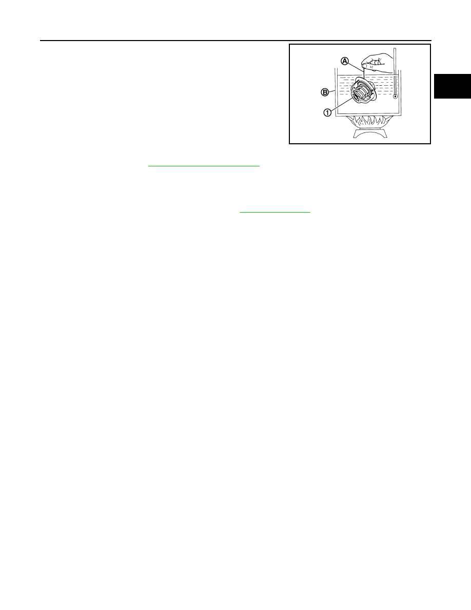
• Place a thread (A) so that it is caught in the valves of water control

valve (1). Immerse fully in a container (B) filled with water. Heat

while stirring.

• The valve opening temperature is the temperature at which the

valve opens and falls from the thread.

• Continue heating. Check the continuous valve lifting toward maxi-

mum valve lift.

NOTE:

The maximum valve lift amount standard temperature for water

control valve is the reference value.

• After checking the maximum valve lift amount, lower the water

temperature and check the valve closing temperature. 

• If out of the standard, replace water control valve.

INSPECTION AFTER INSTALLATION

• Check for leakage of engine coolant using the radiator cap tester adapter (commercial service tool) and the

radiator cap tester (commercial service tool). Refer to 

CO-10, "Inspection"

.

• Start and warm up the engine. Check visually that there is no leakage of engine coolant.

Standard:

Refer to 

CO-28, "Water Control Valve"

.

PBIC3314J

CO-28

< SERVICE DATA AND SPECIFICATIONS (SDS) 

[MR FOR NISMO RS MODELS]

SERVICE DATA AND SPECIFICATIONS (SDS)

SERVICE DATA AND SPECIFICATIONS (SDS)

SERVICE DATA AND SPECIFICATIONS (SDS)

Periodical Maintenance Specification

INFOID:0000000012197538

ENGINE COOLANT CAPACITY (APPROXIMATE)

Unit:   (US qt, Imp qt)

Radiator

INFOID:0000000012197539

Unit: kPa (kg/cm

2

, psi)

Thermostat

INFOID:0000000012197540

Standard

Water Control Valve

INFOID:0000000012197541

Standard

Engine coolant capacity (With reservoir tank at “MAX” level)

M/T models

7.9 (8- 3/8, 7)

CVT models

8.1 (8- 1/2, 7-1/8)

Reservoir tank engine coolant capacity (At “MAX” level)

0.6 (5/8, 1/2)

Cap relief pressure

Standard

78 - 98 (0.8 - 1.0, 11 - 14)

Limit

59 (0.6, 9)

Leakage testing pressure

98 (1.0, 14)

Valve opening temperature

80.5 - 83.5

°C (177 - 182°F)

Maximum valve lift

8.0 mm/95

°C (0.315 in/203°F)

Valve closing temperature

77

°C (171°F)

Valve opening temperature

93.5 - 96.5

°C (200 - 206°F)

Maximum valve lift

8.0 mm/108

°C (0.315 in/226°F)

Valve closing temperature

90

°C (194°F)

PRECAUTIONS

CO-29

< PRECAUTION >

[MR EXCEPT FOR NISMO RS MODELS]

C

D

E

F

G

H

I

J

K

L

M

A

CO

N

P

O

PRECAUTION

PRECAUTIONS

Precautions for Removing Battery Terminal

INFOID:0000000012959273

When disconnecting the battery terminal, pay attention to the following.

• Always use a 12V battery as power source.

• Never disconnect battery terminal while engine is running.

• When removing the 12V battery terminal, turn OFF the ignition

switch and wait at least 30 seconds.

• For vehicles with the engine listed below, remove the battery termi-

nal after a lapse of the specified time:

NOTE:

ECU may be active for several tens of seconds after the ignition switch is turned OFF. If the battery terminal

is removed before ECU stops, then a DTC detection error or ECU data corruption may occur.

• After high-load driving, if the vehicle is equipped with the V9X engine, turn the ignition switch OFF and wait

for at least 15 minutes to remove the battery terminal.

NOTE:

• Turbocharger cooling pump may operate in a few minutes after the ignition switch is turned OFF.

• Example of high-load driving

- Driving for 30 minutes or more at 140 km/h (86 MPH) or more.

- Driving for 30 minutes or more on a steep slope.

• For vehicles with the 2-batteries, be sure to connect the main battery and the sub battery before turning ON

the ignition switch.

NOTE:

If the ignition switch is turned ON with any one of the terminals of main battery and sub battery discon-

nected, then DTC may be detected.

• After installing the 12V battery, always check "Self Diagnosis Result" of all ECUs and erase DTC.

NOTE:

The removal of 12V battery may cause a DTC detection error.

Precaution for Supplemental Restraint System (SRS) "AIR BAG" and "SEAT BELT 
PRE-TENSIONER"

INFOID:0000000012197542

The Supplemental Restraint System such as “AIR BAG” and “SEAT BELT PRE-TENSIONER”, used along

with a front seat belt, helps to reduce the risk or severity of injury to the driver and front passenger for certain

types of collision. This system includes seat belt switch inputs and dual stage front air bag modules. The SRS

system uses the seat belt switches to determine the front air bag deployment, and may only deploy one front

air bag, depending on the severity of a collision and whether the front occupants are belted or unbelted.

Information necessary to service the system safely is included in the “SRS AIR BAG” and “SEAT BELT” of this

Service Manual.

WARNING:

Always observe the following items for preventing accidental activation.

• To avoid rendering the SRS inoperative, which could increase the risk of personal injury or death in

the event of a collision that would result in air bag inflation, it is recommended that all maintenance

and repair be performed by an authorized NISSAN/INFINITI dealer.

• Improper repair, including incorrect removal and installation of the SRS, can lead to personal injury

caused by unintentional activation of the system. For removal of Spiral Cable and Air Bag Module,

see “SRS AIR BAG”.

D4D engine

: 20 minutes

YS23DDT

: 4 minutes

HRA2DDT

: 12 minutes

YS23DDTT

: 4 minutes

K9K engine

: 4 minutes

ZD30DDTi

: 60 seconds

M9R engine

: 4 minutes

ZD30DDTT

: 60 seconds

R9M engine

: 4 minutes

V9X engine

: 4 minutes

YD25DDTi

: 2 minutes

SEF289H

CO-30

< PRECAUTION >

[MR EXCEPT FOR NISMO RS MODELS]

PRECAUTIONS

• Never use electrical test equipment on any circuit related to the SRS unless instructed to in this Ser-

vice Manual. SRS wiring harnesses can be identified by yellow and/or orange harnesses or harness

connectors.

PRECAUTIONS WHEN USING POWER TOOLS (AIR OR ELECTRIC) AND HAMMERS

WARNING:

Always observe the following items for preventing accidental activation.

• When working near the Air Bag Diagnosis Sensor Unit or other Air Bag System sensors with the

ignition ON or engine running, never use air or electric power tools or strike near the sensor(s) with

a hammer. Heavy vibration could activate the sensor(s) and deploy the air bag(s), possibly causing

serious injury.

• When using air or electric power tools or hammers, always switch the ignition OFF, disconnect the

battery or batteries, and wait at least 3 minutes before performing any service.

Precautions Necessary for Steering Wheel Rotation after Battery Disconnect

INFOID:0000000012197544

NOTE:

• Before removing and installing any control units, first turn the push-button ignition switch to the LOCK posi-

tion, then disconnect both battery cables.

• After finishing work, confirm that all control unit connectors are connected properly, then re-connect both

battery cables.

• Always use CONSULT-II to perform self-diagnosis as a part of each function inspection after finishing work.

If a DTC is detected, perform trouble diagnosis according to self-diagnosis results.

This vehicle is equipped with a push-button ignition switch and a steering lock unit.

If the battery is disconnected or discharged, the steering wheel will lock and cannot be turned.

If turning the steering wheel is required with the battery disconnected or discharged, follow the procedure

below before starting the repair operation.

OPERATION PROCEDURE

1. Connect both battery cables.

NOTE:

Supply power using jumper cables if battery is discharged.

2. Carry the Intelligent Key or insert it to the key slot and turn the push-button ignition switch to ACC position.

(At this time, the steering lock will be released.)

3. Disconnect both battery cables. The steering lock will remain released with both battery cables discon-

nected and the steering wheel can be turned.

4. Perform the necessary repair operation.
5. When the repair work is completed, re-connect both battery cables. With the brake pedal released, turn

the push-button ignition switch from ACC position to ON position, then to LOCK position. (The steering

wheel will lock when the push-button ignition switch is turned to LOCK position.)

6. Perform self-diagnosis check of all control units using CONSULT-II.


Content   ..  184  185  186  187   ..