Nissan Juke F15. Manual - part 167
CHG
COMPONENT PARTS
CHG-7
< SYSTEM DESCRIPTION >
C
D
E
F
G
H
I
J
K
L
B
A
O
P
N
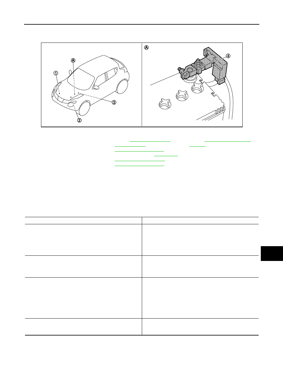
Parts Location
INFOID:0000000012200363
POWER GENERATION VOLTAGE VARIABLE CONTROL SYSTEM : Component De-
scription
INFOID:0000000012200364
1.
Alternator
2.
ECM
Refer to
TROL SYSTEM :
Component Parts Location"
(For
NISMO RS models) or
GINE CONTROL SYSTEM :
Component Parts Location"
(Ex-
cept for NISMO RS models)
3.
IPDM E/R
Refer to
4.
Battery current sensor (with battery
temperature sensor)
A.
Battery
JMMIA0483ZZ
Component part
Description
Alternator (IC voltage regulator)
IC voltage regulator controls the power generation voltage by the
target power generation voltage based on the received power gen-
eration command signal.
When there is no power generation command signal, the alterna-
tor performs the normal power generation according to the char-
acteristic of the IC voltage regulator.
Battery current sensor (with battery temperature sensor)
Battery current sensor is installed to the battery cable at the neg-
ative terminal, and it detects the charging/discharging current of
the battery and sends the voltage signal to ECM according to the
current value.
ECM
Battery current sensor detects the charging/discharging current of
the battery. ECM judges the battery condition based on this signal.
ECM judges whether to perform the power generation voltage
variable control according to the battery condition.
When performing the power generation voltage variable control,
ECM calculates the target power generation voltage according to
the battery condition and sends the calculated value as the power
generation command value signal to IPDM E/R.
IPDM E/R
IPDM E/R converts the received power generation command val-
ue into the power generation command signal (PWM signal) and
sends it to the IC voltage regulator.