Content .. 1325 1326 1327 1328 ..
Nissan Juke F15. Manual - part 1327
TM-498
< DTC/CIRCUIT DIAGNOSIS >
[CVT: RE0F10D]
P0847 TRANSMISSION FLUID PRESSURE SEN/SW B
P0847 TRANSMISSION FLUID PRESSURE SEN/SW B
DTC Logic
INFOID:0000000012201196
DTC DETECTION LOGIC
DTC CONFIRMATION PROCEDURE
1.
PREPARATION BEFORE WORK
If another "DTC CONFIRMATION PROCEDURE" occurs just before, turn ignition switch OFF and wait for at
least 10 seconds, then perform the next test.
>> GO TO 2.
2.
CHECK DTC DETECTION
With CONSULT
1. Start the engine.
2. Select “Data Monitor” in “TRANSMISSION”.
3. Select “FLUID TEMP”.
4. Maintain the following conditions for 10 seconds or more.
5. Check the first trip DTC.
With GST
1. Start the engine and wait for at least 10 seconds.
CAUTION:
When the ambient temperature is less than
−20°C (−4°F) and the engine is cold, warm up the
engine for approximately 5 minutes.
2. Check the first trip DTC.
Is “P0847”detected?
YES
>> Go to
NO
>> INSPECTION END
Diagnosis Procedure
INFOID:0000000012201197
1.
CHECK TCM INPUT SIGNALS
1. Turn ignition switch OFF.
2. Start the engine.
3. Check voltage between TCM harness connector terminals.
Is the inspection result normal?
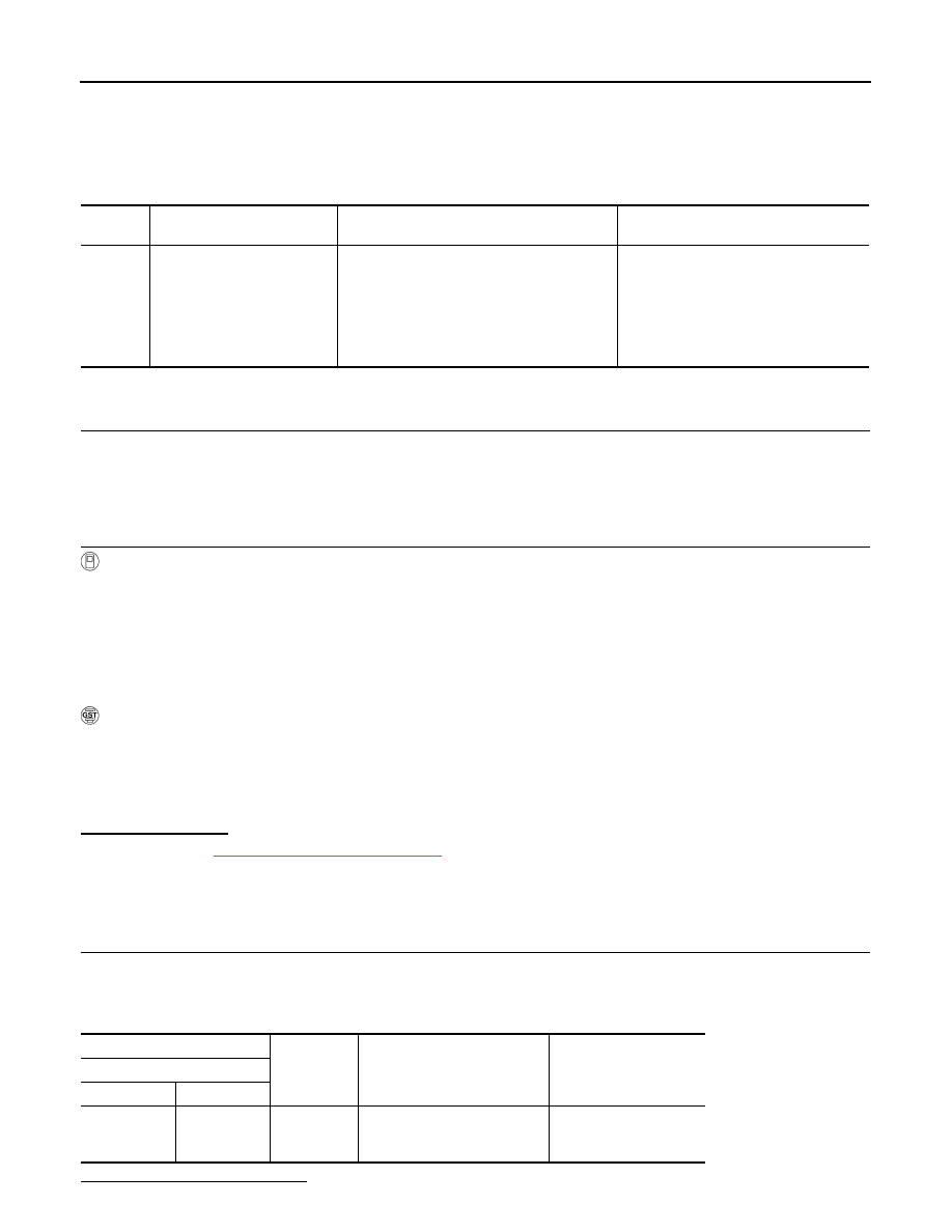
DTC
CONSULT screen terms
(Trouble diagnosis content)
DTC detection condition
Possible causes
P0847
FLUID PRESS SEN/SW B
(Transmission Fluid Pressure
Sensor/Switch B Circuit Low)
When all of the following conditions are satis-
fied and this state is maintained for 5 seconds:
• CVT fluid temperature: More than
−20°C (−
4
°F)
• TCM power supply voltage: 11 V or more
• Secondary pressure sensor voltage: 0.09 V
or less
• Harness or connector
(Secondary pressure sensor circuit is
open or shorted to ground)
• Secondary pressure sensor
• Control valve assembly
FLUID TEMP
:
−20°C (−4°F)
+
−
Condition
Voltage
TCM
Connector
Terminal
F83
16
Ground
• After engine warm up
• Selector lever: “N” position
• At idle
1.2 – 1.3 V