Content .. 1274 1275 1276 1277 ..
Nissan Juke F15. Manual - part 1276
TM-294
< DTC/CIRCUIT DIAGNOSIS >
[CVT: RE0F10B]
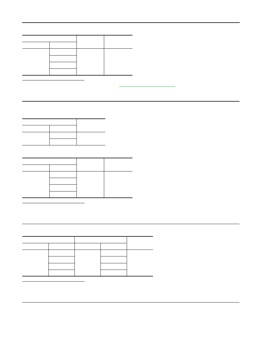
P1777 STEP MOTOR
Check resistance between TCM harness connector terminals and ground.
Is the inspection result normal?
YES
>> Check intermittent incident. Refer to
GI-45, "Intermittent Incident"
.
NO
>> GO TO 3.
3.
CHECK STEP MOTOR
1. Disconnect CVT unit connector.
2. Check resistance between CVT unit connector terminals.
3. Check resistance between CVT unit connector terminals and ground.
Is the inspection result normal?
YES
>> GO TO 4.
NO
>> GO TO 6.
4.
CHECK CIRCUIT BETWEEN TCM AND CVT UNIT (STEP MOTOR) (PART 1)
Check continuity between TCM harness connector terminals and CVT unit harness connector terminals.
Is the inspection result normal?
YES
>> GO TO 5.
NO
>> Repair or replace damaged parts.
5.
CHECK CIRCUIT BETWEEN TCM AND CVT UNIT (STEP MOTOR) (PART 2)
Check continuity between TCM harness connector terminals and ground.
TCM
Ground
Resistance
Connector
Terminal
F81
27
Ground
Approx. 15.0
Ω
28
29
30
CVT unit
Resistance
Connector
Terminal
F209
6 – 7
Approx. 30.0
Ω
8 – 9
CVT unit
Ground
Resistance
Connector
Terminal
F209
6
Ground
Approx. 15.0
Ω
7
8
9
TCM
CVT unit
Continuity
Connector
Terminal
Connector
Terminal
F81
27
F51
9
Existed
28
8
29
7
30
6