Content .. 1254 1255 1256 1257 ..
Nissan Juke F15. Manual - part 1256
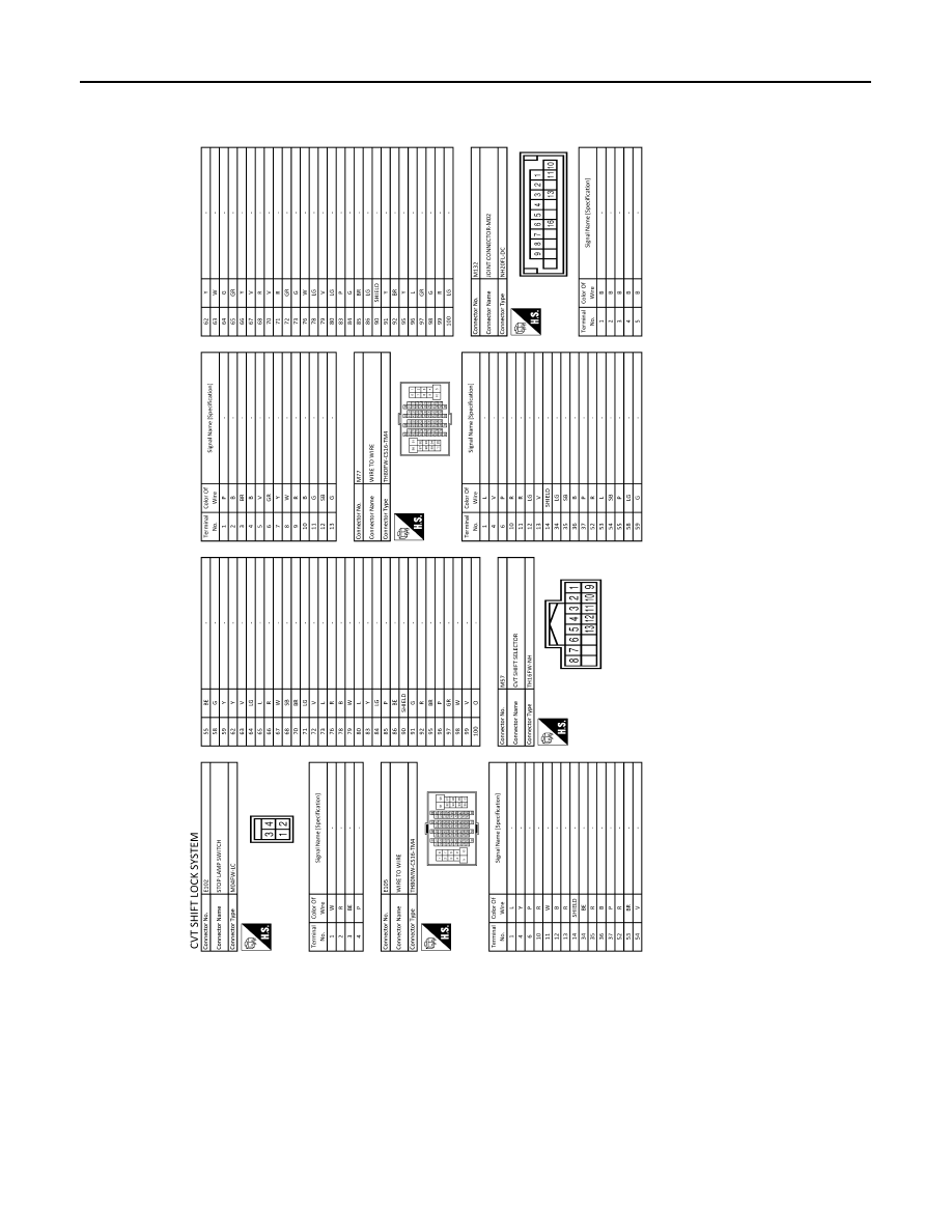
TM-214
< WIRING DIAGRAM >
[CVT: RE0F10B]
CVT SHIFT LOCK SYSTEM
JRDWC6640GB
|
|
|
Content .. 1254 1255 1256 1257 ..
TM-214 < WIRING DIAGRAM > [CVT: RE0F10B] CVT SHIFT LOCK SYSTEM JRDWC6640GB |