Content .. 1189 1190 1191 1192 ..
Nissan Juke F15. Manual - part 1191
STC-20
< BASIC INSPECTION >
DIAGNOSIS AND REPAIR WORKFLOW
Other conditions
Memo
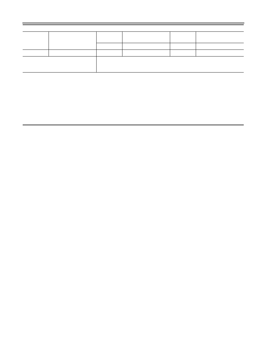
Interview sheet
Customer
name
MR/MS
Registration
number
Initial year
registration
Vehicle type
VIN
Storage date
Engine
Mileage
km (Mile)