Content .. 1069 1070 1071 1072 ..
Nissan Juke F15. Manual - part 1071
POWER WINDOW MOTOR
PWC-37
< DTC/CIRCUIT DIAGNOSIS >
C
D
E
F
G
H
I
J
L
M
A
B
PWC
N
O
P
REAR LH : Component Function Check
INFOID:0000000012196928
1.
CHECK FUNCTION
Check rear power window motor LH operation with rear power window switch LH or power window main
switch (rear LH switch).
Is the inspection result normal?
YES
>> INSPECTION END
NO
>> Refer to
PWC-37, "REAR LH : Diagnosis Procedure"
.
REAR LH : Diagnosis Procedure
INFOID:0000000012196929
1.
CHECK REAR POWER WINDOW MOTOR LH INPUT SIGNAL
1. Turn ignition switch OFF.
2. Disconnect rear power window motor LH connector.
3. Turn ignition switch ON.
4. Check voltage between rear power window motor LH harness connector and ground.
Is the inspection result normal?
YES
>> Replace rear power window motor LH. Refer to
GW-23, "Disassembly and Assembly"
.
NO
>> GO TO 2.
2.
CHECK REAR POWER WINDOW MOTOR LH CIRCUIT
1. Turn ignition switch OFF.
2. Disconnect rear power window switch LH connector.
3. Check continuity between rear power window motor LH harness connector and rear power window switch
LH harness connector.
4. Check continuity between rear power window motor LH connector and ground.
Is the inspection result normal?
YES
>> Replace rear power window switch LH. Refer to
PWC-54, "Removal and Installation"
.
NO
>> Repair or replace harness.
REAR RH
REAR RH : Component Function Check
INFOID:0000000012196930
1.
CHECK FUNCTION
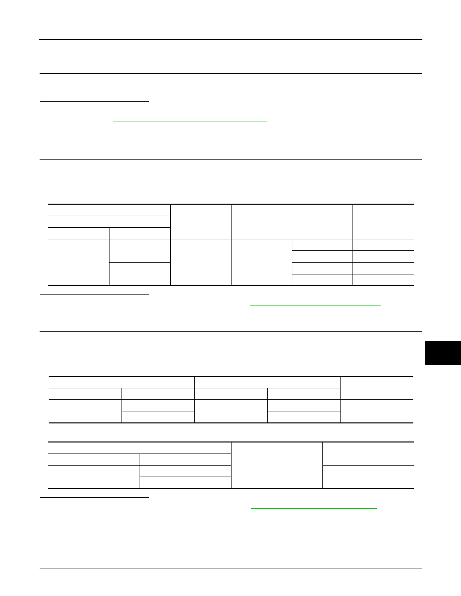
(+)
(-)
Condition
Voltage (V)
Rear power window motor LH
Connector
Terminal
D67
1
Ground
Rear power win-
dow switch LH
NEUTRAL
0 – 1
DOWN
9 – 16
3
NEUTRAL
0 – 1
UP
9 – 16
Rear power window motor LH
Rear power window switch LH
Continuity
Connector
Terminal
Connector
Terminal
D67
1
D63
4
Existed
3
5
Rear power window motor LH
Ground
Continuity
Connector
Terminal
D67
1
Not existed
3