Nissan Tiida C11. Manual - part 865


  Главная      Nissan     Nissan Tiida C11 - Service Manual


поиск по сайту            


содержание   ..  863  864  865  866   ..


Nissan Tiida C11. Manual - part 865


HAC-124

< COMPONENT DIAGNOSIS >

[AUTO AIR CONDITIONER (W/O NAVI)]

MAGNET CLUTCH

MAGNET CLUTCH

System Description

INFOID:0000000001547430

SYSTEM DESCRIPTION

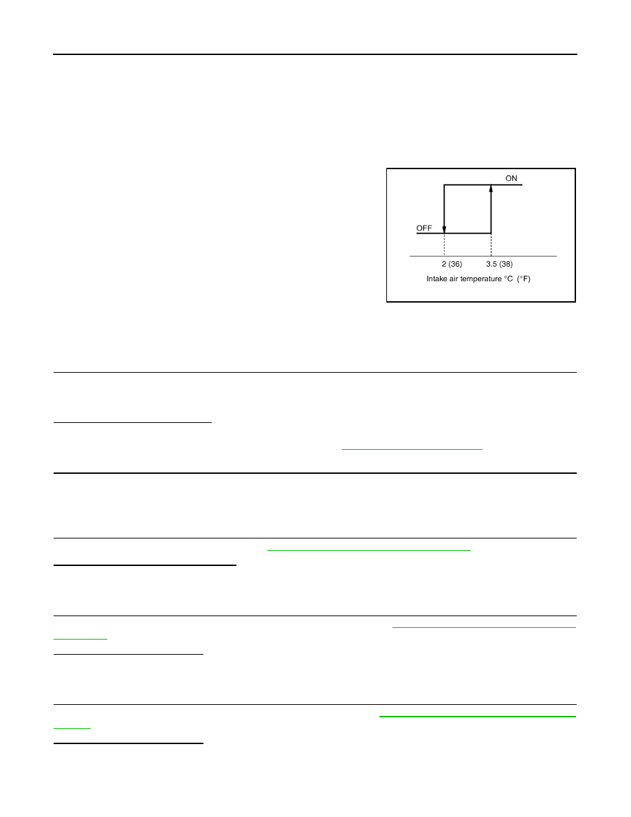
Front air control controls compressor operation by intake air temperature and signal from ECM.

Low Temperature Protection Control

Front air control will turn compressor ON or OFF as determined by a signal detected by intake sensor.
When intake air temperatures are higher than 3.5

°

C (38

°

F), the com-

pressor turns ON. The compressor turns OFF when intake air tem-
peratures are lower than 2

°

C (36

°

F).

Magnet Clutch Component Function Check

INFOID:0000000001569476

INSPECTION FLOW

1.

CONFIRM SYMPTOM BY PERFORMING OPERATIONAL CHECK - A/C SWITCH

1.

Press the AUTO switch and A/C switch.

2.

The A/C switch indicator will illuminate. Confirm that the compressor clutch engages (sound or visual
inspection).

Can the symptom be duplicated?

YES

>> GO TO 2.

NO

>> Perform a complete operational check. Refer to 

HAC-87, "Operational Check"

.

2.

CHECK FOR SERVICE BULLETINS

Check for any service bulletins.

>> GO TO 3.

3.

PERFORM SELF-DIAGNOSIS.

Perform the self-diagnosis function. Refer to 

HAC-98, "Front Air Control Self-Diagnosis"

.

Are any self-diagnosis codes present?

YES

>> Repair as necessary.

NO

>> GO TO 4.

4.

 CHECK AMBIENT SENSOR CIRCUIT

Perform diagnostic procedure for the ambient sensor circuit. Refer to 

HAC-130, "Ambient Sensor Diagnosis

Procedure"

.

Is the inspection result normal?

YES

>> GO TO 5.

NO

>> Repair as necessary.

5.

 CHECK INTAKE SENSOR CIRCUIT

Perform diagnostic procedure for the intake sensor circuit. Refer to 

HAC-139, "Intake Sensor Diagnosis Pro-

cedure"

.

Is the inspection result normal?

YES

>> GO TO 6.

NO

>> Repair as necessary.

SJIA0802E

MAGNET CLUTCH

HAC-125

< COMPONENT DIAGNOSIS >

[AUTO AIR CONDITIONER (W/O NAVI)]

C

D

E

F

G

H

J

K

L

M

A

B

HAC

N

O

P

6.

 RECHECK FOR SYMPTOMS 

Perform a complete operational check and check for any symptoms. Refer to 

HAC-87, "Operational Check"

.

Does another symptom exist?

YES

>> Repair as necessary.

NO

>> Replace front air control. Refer to XX.

Magnet Clutch Diagnosis Procedure

INFOID:0000000001547432

DIAGNOSTIC PROCEDURE FOR MAGNET CLUTCH

SYMPTOM: Magnet clutch does not engage when A/C switch is ON.

1.

CHECK INTAKE SENSOR CIRCUIT

Refer to 

HAC-139, "Intake Sensor Diagnosis Procedure"

.

Is the inspection result normal?

YES

>> GO TO 2.

NO

>> Malfunctioning intake sensor: Refer to XX.

2.

PERFORM AUTO ACTIVE TEST

Refer to 

XX-XX, "*****"

.

Does the magnet clutch operate?

YES

>> •

WITH CONSULT-III

GO TO 6.

WITHOUT CONSULT-III

GO TO 7.

NO

>> GO TO 3.

3.

CHECK POWER SUPPLY FOR MAGNET CLUTCH 

1.

Turn ignition switch OFF. 

2.

Disconnect compressor connector F3.

3.

Start the engine.

4.

Press AUTO switch and A/C switch ON.

5.

Check voltage between compressor harness connector F3 ter-
minal 1 and ground. 

AWIIA0304GB

Terminals

Voltage

(Approx.)

(+)

(

)

Connector

Terminal 

Ground

Compressor: F3

1

12V

SJIA0743E

HAC-126

< COMPONENT DIAGNOSIS >

[AUTO AIR CONDITIONER (W/O NAVI)]

MAGNET CLUTCH

Is the inspection result normal?

YES

>> Replace A/C compressor. Refer to 

XX-XX, "*****"

.

NO

>>

Check 10A fuse (No. 42), located in the IPDM E/R. 

• If fuse is OK, GO TO 4. 
• If fuse is NG, replace fuse and check harness for short circuit. Repair or replace if necessary.

4.

CHECK MAGNET CLUTCH CIRCUIT

Check for operation sound when applying battery voltage direct cur-
rent to terminal.
Is the inspection result normal?

OK

>> GO TO 5. 

NO

>> Replace A/C compressor. Refer to 

XX-XX, "*****"

.

5.

CHECK CIRCUIT CONTINUITY BETWEEN IPDM E/R AND COMPRESSOR

1.

Turn ignition switch OFF.

2.

Disconnect IPDM E/R connector E43.

3.

Check continuity between compressor harness connector F3 (A)
terminal 1 and IPDM E/R harness connector E43 (B) terminal
11.

Is the inspection result normal?

YES

>> Replace IPDM E/R. Refer to 

XX-XX, "*****"

.

NO

>> Repair harness or connector.

6.

CHECK BCM INPUT (COMPRESSOR ON) SIGNAL

Check compressor ON/OFF signal. Refer to 

HAC-97, "CONSULT-III Function (BCM)"

.

Is the inspection result normal?

YES

>> GO TO 9.

NO

>> GO TO 7.

7.

CHECK CIRCUIT CONTINUITY BETWEEN FRONT AIR CONTROL AND BCM.

1.

Turn ignition switch OFF.

2.

Disconnect front air control harness connector M50.

3.

Disconnect BCM harness connector M19.

4.

Check continuity between front air control harness connector
M33 (A) terminal 13 and BCM harness connector M19 (B) termi-
nal 61.

5.

Check continuity between front air control harness connector M33 (A) terminal 13 and ground.

RJIA2005E

A

B

Continuity

Connector

Terminal

Connector

Terminal

Yes

Compressor: 

F3

1

IPDM E/R: 

E43

11

AWIIA0305ZZ

A/C SW ON

: AIR COND SW ON

A/C SW OFF

: AIR COND SW OFF

A

B

Continuity

Connector

Terminal

Connector

Terminal

Front air control: 

M50

13

BCM: M19

61

Yes

AWIIA0565ZZ

MAGNET CLUTCH

HAC-127

< COMPONENT DIAGNOSIS >

[AUTO AIR CONDITIONER (W/O NAVI)]

C

D

E

F

G

H

J

K

L

M

A

B

HAC

N

O

P

Is the inspection result normal?

YES

>> GO TO 8.

NO

>> Repair harness or connector.

8.

CHECK VOLTAGE FOR FRONT AIR CONTROL (COMPRESSOR ON SIGNAL)

1.

Reconnect front air control harness connector M50 and BCM
harness connector M19.

2.

Turn ignition switch ON.

3.

Confirm compressor ON signal between front air control harness
connector M50 terminal 13 and ground.

Is the inspection result normal?

YES

>> GO TO 9.

NO

>> Replace front air control. Refer to XX.

9.

CHECK REFRIGERANT PRESSURE SENSOR

WITH CONSULT-III

1.

Start the engine.

2.

Check the voltage of refrigerant pressure sensor. Refer to 

XX-XX, "*****"

.

WITHOUT CONSULT-III

1.

Start the engine.

2.

Check voltage between ECM harness connector F11 and
ground.

Is the inspection result normal?

YES

>> •

WITH CONSULT-III

GO TO 10.

WITHOUT CONSULT-III

GO TO 11.

NO

>> Refer to 

XX-XX, "*****"

.

10.

CHECK BCM INPUT (FAN ON) SIGNAL

Check FAN ON/OFF signal. Refer to 

HAC-97, "CONSULT-III Function (BCM)"

.

A

Ground

Continuity

Connector

Terminal

Front air control: 

M50

13

No

Terminals

Condition

Voltage

(Approx.)

(+)

(-)

Connector

Terminal 

Ground

Front air 

control: 

M50

13

A/C switch: 
ON
(Blower mo-
tor oper-
ates.)

AWIIA0486ZZ

ZJIA0584J

Terminals

Condition

Voltage

(Approx.)

(+)

(-)

Connector

Terminal 

 ECM: F11

41 without 

diesel

Ground

A/C switch: ON
(Blower motor 
operates.)

1-4V

78 with diesel

AWIIA0562ZZ


содержание   ..  863  864  865  866   ..