содержание .. 741 742 743 744 ..
Nissan Tiida C11. Manual - part 743
EM-324
< DISASSEMBLY AND ASSEMBLY >
[K9K]
CYLINDER BLOCK
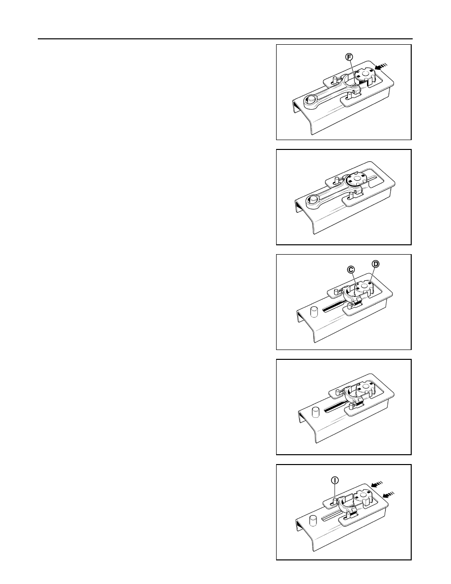
d.
Lay the connecting rod bearing [with a width of 20.625 mm
(0.8120 in)] (F) on the connecting rod bearing support, then
push it in the direction of the arrow (as shown).
e.
Bring the connecting rod support up against the base of the con-
necting rod body.
f.
Remove the connecting rod body support and repeat the opera-
tion for the remaining connecting rod bodies.
g.
Position the connecting rod bearing support either on the
engraved mark (C) if the width of the connecting rod bearing is
equal to 20.625 mm (0.8120 in).
h.
Position the connecting rod bearing support either on the
engraved mark (D) if the width of the connecting rod bearing is
equal to 17.625 mm (0.6939 in).
i.
Install the connecting rod cap as shown.
j.
Push the guide (in the direction of the arrow) until the connecting
rod cap is in contact with the pins (I) on the base of the tool.
MBIB0465E
MBIB0466E
MBIB0467E
MBIB0468E
MBIB0469E