содержание .. 726 727 728 729 ..
Nissan Tiida C11. Manual - part 728
EM-264
< ON-VEHICLE MAINTENANCE >
[K9K]
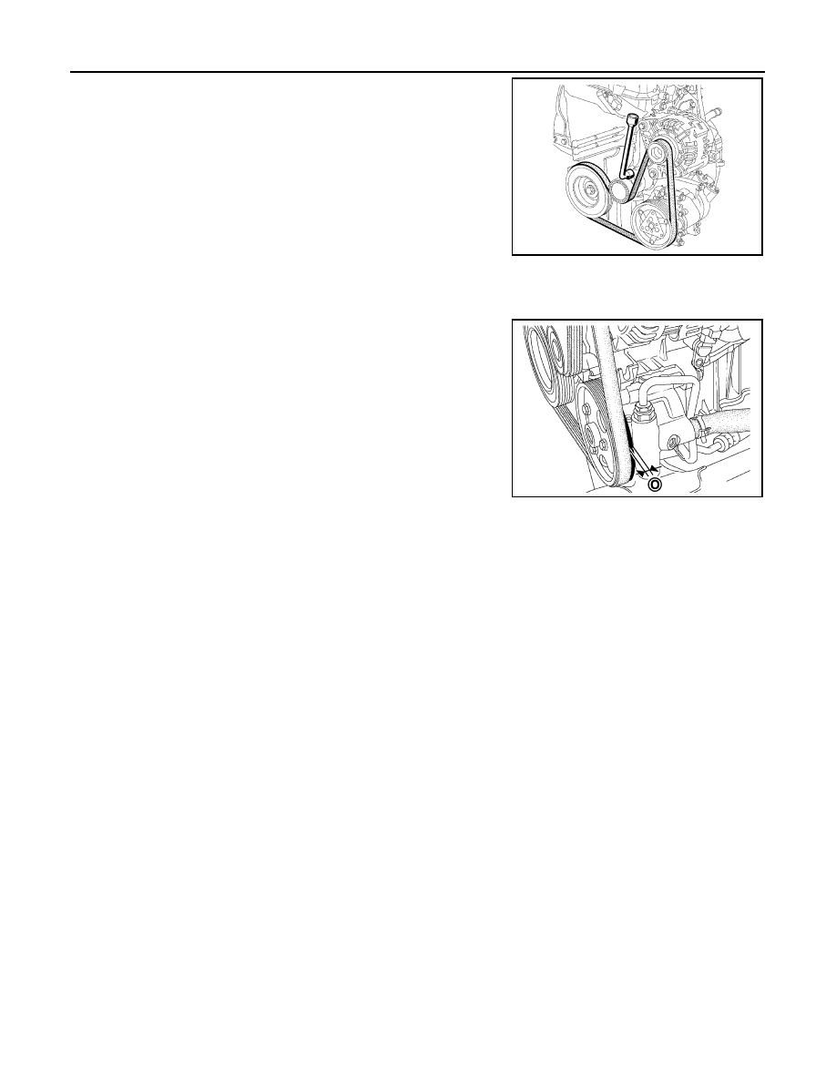
DRIVE BELTS
4.
Remove drive belt.
• Turn drive belt auto-tensioner adjusting bolt clockwise to
release drive belt tension.
INSTALLATION
1.
Install the drive belt.
CAUTION:
• Make sure drive belt is correctly engaged with the pulley
groove.
• Check for oil and coolant on drive belt and each pulley
groove.
• Certain drive belts have five teeth whereas the air condi-
tioning compressor pulley, power-assisted steering pump
pulley, and generator pulley all have six teeth.In this case,
it is essential to check that inner tooth (O) of the pulleys
remains free when fitting the drive belt.
Never turn the engine in the opposite direction to its nor-
mal operating direction.
Use a brush to remove any deposits from the crankshaft
pulley V grooves.
2.
Release drive belt auto-tensioner, and apply tension to drive belt.
3.
Turn crankshaft pulley clockwise several times to equalize tension between each pulley.
MBIB0353E
MBIB0516E