Nissan Tiida C11. Manual - part 712


  Главная      Nissan     Nissan Tiida C11 - Service Manual


поиск по сайту            


содержание   ..  710  711  712  713   ..


Nissan Tiida C11. Manual - part 712


EM-200

< ON-VEHICLE REPAIR >

[MR18DE]

CYLINDER HEAD

: Engine front

CAUTION:

Check and confirm the tightening angle by using Tool (A) or
protractor. Never judge by visual inspection without the
tool.

4.

Installation of the remaining components is in the reverse order of removal.
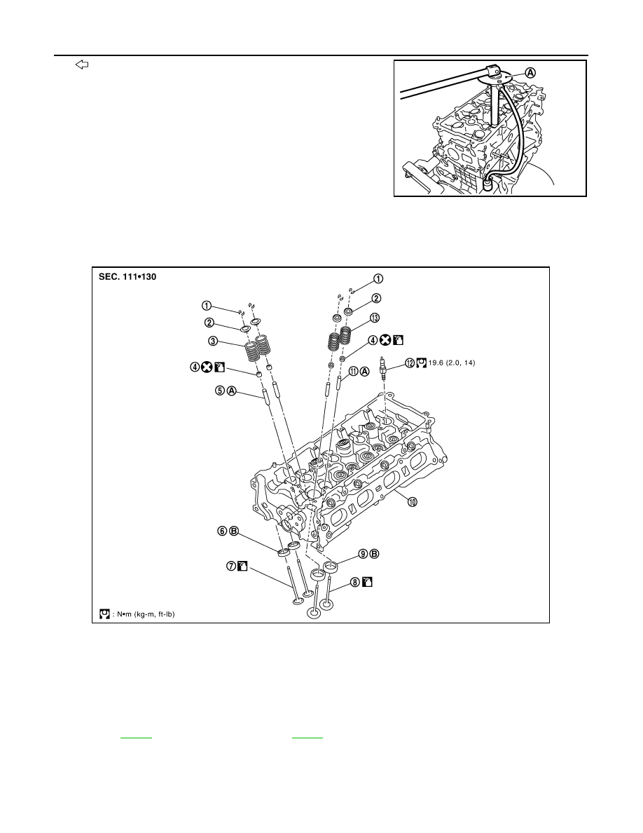
Component

INFOID:0000000001337806

Disassembly and Assembly

INFOID:0000000001337807

DISASSEMBLY

Tool number

: KV10112100 (BT-8653-A)

PBIC3208J

1.

Valve collet

2.

Valve spring retainer

3.

Valve spring (EXH)                                     
(with valve spring seat)

4.

Valve oil seal

5.

Valve guide (EXH)

6.

Valve seat (EXH)

7.

Valve (EXH)

8.

Valve (INT)

9.

Valve seat (INT)

10. Cylinder head

11. Valve guide (INT)

12. Spark plug

13.

Valve spring (INT)
(with valve spring seat)

A.

Refer to 

EM-202

B.

Refer to 

EM-202

PBIC3543J

CYLINDER HEAD

EM-201

< ON-VEHICLE REPAIR >

[MR18DE]

C

D

E

F

G

H

I

J

K

L

M

A

EM

N

P

O

1.

Remove spark plug using suitable tool.

2.

Remove valve lifter.
• Identify installation positions, and store them without mixing them up.

3.

Remove valve collet. 
• Compress valve spring using Tool, attachment and adapter

(A). Remove valve collet using a suitable magnet hand.

CAUTION:

When working, be careful not to damage valve lifter holes.

4.

Remove valve spring retainer and valve spring (with valve spring seat).

CAUTION:

Never remove valve spring seat from valve spring.

5.

Push valve stem to combustion chamber side, and remove valve. 
NOTE:
Identify installed positions, and store them without mixing them up.

6.

Remove valve oil seal using Tool (A).

7.

When valve seat must be replaced, refer to 

EM-202, "Inspection After Disassembly"

 to removal.

8.

When valve guide must be replaced, refer to 

EM-202, "Inspection After Disassembly"

 to removal.

ASSEMBLY

1.

Install valve guide if removed. Refer to 

EM-202, "Inspection After Disassembly"

.

2.

Install valve seat if removed. Refer to 

EM-202, "Inspection After Disassembly"

.

3.

Install valve oil seal.
• Install with a valve oil seal using Tool (A) to match dimension

as shown.

NOTE:
Dimension “H” is height that measured before installing valve
spring (with valve spring seat).

4.

Install valve.
• Install larger diameter to intake side.

Tool number

: KV101092S0 (J-26336-B)

PBIC3209J

Tool number

: KV10107902 (J-38959)

PBIC3210J

Tool number

: KV10115600 (J-38958)

Height “H”

: 15.1 - 15.7 mm (0.594 - 0.618 in)

PBIC3211J

EM-202

< ON-VEHICLE REPAIR >

[MR18DE]

CYLINDER HEAD

5.

Install valve spring (with valve spring seat).
• Install smaller pitch (valve spring seat side) to cylinder head

side (B).

• Confirm identification color (A) of valve spring.

6.

Install valve spring retainer.

7.

Install valve collet.
• Compress valve spring using Tool (A). Install valve collet with a magnet hand.

CAUTION:

When working, be careful not to damage valve lifter holes.

• Tap valve stem edge lightly with a plastic hammer after instal-

lation to check its installed condition.

8.

Install valve lifter.
• Install it in the original position.

9.

Install spark plug using suitable tool.

Inspection After Disassembly

INFOID:0000000001337808

VALVE DIMENSIONS

• Check dimensions of each valve. For dimensions, refer to 

EM-238, "Standard and Limit"

.

• If dimensions are out of the standard, replace valve.

VALVE GUIDE CLEARANCE

Valve Stem Diameter

Measure the diameter of valve stem with a micrometer (A).

Valve Guide Inner Diameter

Measure the inner diameter of valve guide with a bore gauge.

Valve Guide Clearance

(Valve guide clearance) = (Valve guide inner diameter) – (Valve stem diameter).

1

: Valve spring seat (Do not remove from valve spring.)

Intake

: White

Exhaust

: Orange

PBIC3462J

Tool number

: KV101092S0 (J-26336 B)

PBIC3209J

Standard

Intake

: 5.465 - 5.480 mm (0.2152 - 0.2157 in)

Exhaust

: 5.455 - 5.470 mm (0.2148 - 0.2154 in)

PBIC3213J

Standard

: 5.500 - 5.518 mm (0.2165 - 0.2172 in)

CYLINDER HEAD

EM-203

< ON-VEHICLE REPAIR >

[MR18DE]

C

D

E

F

G

H

I

J

K

L

M

A

EM

N

P

O

• If it exceeds the limit, replace valve guide and/or valve.

VALVE GUIDE REPLACEMENT

When valve guide is removed, replace with oversized [0.2 mm (0.008 in)] valve guide.

1.

To remove valve guide, heat cylinder head to 110

°

 to 130

°

C

(230

°

 to 266

°

F) by soaking in heated oil (A).

2.

Drive out valve guide using suitable tools.

CAUTION:

Cylinder head contains heat, when working, wear protective
equipment to avoid getting burned.

3.

Ream cylinder head valve guide hole using suitable tool (A).

Valve guide clearance:

Standard

Intake

: 0.020 - 0.053 mm (0.0008 - 0.0021 in)

Exhaust

: 0.030 - 0.063 mm (0.0012 - 0.0025 in)

Limit

: 0.1 mm (0.004 in)

PBIC3214J

SEM931C

Valve guide hole diameter (for service parts):

: 9.675 - 9.696 mm (0.3809 - 0.3817 in)

PBIC3215J


содержание   ..  710  711  712  713   ..