Nissan Tiida C11. Manual - part 708


  Главная      Nissan     Nissan Tiida C11 - Service Manual


поиск по сайту            


содержание   ..  706  707  708  709   ..


Nissan Tiida C11. Manual - part 708


EM-184

< ON-VEHICLE REPAIR >

[MR18DE]

TIMING CHAIN

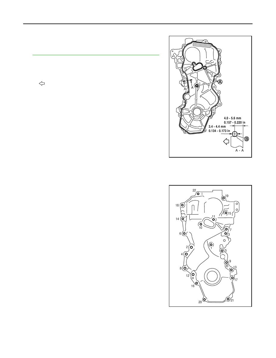
Be sure O-rings a aligned properly.

13. Apply the sealant without breaks to the specified location using

Tool. 
Use Genuine Silicone RTV Sealant or equivalent. Refer to

GI-27, "Recommended Chemical Products and Sealants"

.

14. Make sure that matching marks of timing chain and each sprocket are still aligned. 

CAUTION:

• Make sure O-ring on cylinder block is correctly installed.
• Be careful not to damage front oil seal by interference with front end of crankshaft.

15. Install front cover, and tighten bolts in numerical order as shown.

CAUTION:

Attaching should be done within 5 minutes after liquid gas-
ket application.
NOTE:
Follow the installation position of bolts as shown.

16. Tighten all bolts are in two stages to specified torque in numeri-

cal order as shown.

CAUTION:

Be sure to wipe off any excessive liquid gasket leaking.

17. Install crankshaft pulley. 

CAUTION:

• Never damage front oil seal lip section.
• If needed use a plastic hammer, tap on its center portion (not circumference) to seat crankshaft

pulley.

Tool number

WS39930000 (

)

A

: Liquid gasket application area

: Engine outside

PBIC3959E

M6 bolts

:

No. 1

M10 bolts

:

No. 6, 7, 10, 11, 14

M12 bolts

:

No. 2, 4, 8, 12

M8 bolts

:

Except the above

PBIC3164J

TIMING CHAIN

EM-185

< ON-VEHICLE REPAIR >

[MR18DE]

C

D

E

F

G

H

I

J

K

L

M

A

EM

N

P

O

18. Secure crankshaft pulley (1) using tool (A).

19. Apply new engine oil to thread and seat surfaces of crankshaft

pulley bolt.

20. Tighten crankshaft pulley bolt in three steps.

21. Put a paint mark (B) on crankshaft pulley (2), matching with any

one of six easy to recognize angle marks (A) on crankshaft pul-
ley bolt (1) flange. 

22. Turn another 60 degrees clockwise (angle tightening) using

Tool.
• Check the tightening angle with movement of one angle mark.

23. Make sure that crankshaft rotates clockwise smoothly.
24. Installation of the remaining components is in the reverse order of removal.

Step 1

: 68.6 N·m (7.0 kg-m, 51 ft-lb)

Step 2

: 0 N·m (0 kg-m, 0 ft-lb)

Step 3

: 29.4 N·m (3.0 kg-m, 22 ft-lb)

PBIC3961E

Tool number

: KV10112100 (BT-8653-A)

PBIC3963E

EM-186

< ON-VEHICLE REPAIR >

[MR18DE]

CAMSHAFT

CAMSHAFT

Component

INFOID:0000000001337797

Removal and Installation

INFOID:0000000001337798

REMOVAL

WARNING:

• Put a “CAUTION: FLAMMABLE” sign in the workshop.
• Be sure to work in a well ventilated area and furnish workshop with a CO

2

   fire extinguisher. 

• Do not smoke while servicing fuel system. Keep open flames and sparks away from the work area.

1.

Release the fuel pressure. Refer to 

EC-1035, "Inspection"

.

2.

Disconnect negative battery cable. Refer to 

PG-6, "Removal and Installation"

.

3.

Remove front RH wheel. Refer to 

WT-6, "Rotation"

.

4.

Remove front fender protector (RH). Refer to 

EXT-22, "Removal and Installation"

.

5.

Drain engine coolant. Refer to 

CO-35, "Changing Engine Coolant"

.

NOTE:
Perform this step when engine is cold.

6.

Remove the following parts.
• Intake manifold; Refer to 

EM-156

.

• Rocker cover; Refer to 

EM-173, "Removal and Installation"

.

1.

O-ring

2.

Camshaft position sensor (PHASE)

3.

Camshaft bracket

4.

Camshaft sprocket (EXH)

5.

Camshaft sprocket (INT)

6.

Camshaft (EXH)

7.

Camshaft (INT)

8.

Valve lifter (EXH)

9.

Valve lifter (INT)

10. Cylinder head

A.

Refer to 

EM-186

.

PBIC4589E

CAMSHAFT

EM-187

< ON-VEHICLE REPAIR >

[MR18DE]

C

D

E

F

G

H

I

J

K

L

M

A

EM

N

P

O

• Fuel tube and fuel injector assembly; Refer to 

EM-162

.

• Front cover, timing chain and related parts; Refer to 

EM-176

.

7.

Remove camshaft position sensor (PHASE) from camshaft bracket.

CAUTION:

• Handle carefully to avoid dropping and shocks.
• Never disassemble.
• Never allow metal powder to adhere to magnetic part at sensor tip.
• Never place sensor in a location where it is exposed to magnetism.

8.

Put the matching mark (A) on the camshaft sprocket (INT) (2)
and the camshaft bracket (1) as shown.

NOTE:
It prevents the knock pin of the camshaft (INT) from engaging
with the incorrect pin hole when installing the camshaft sprocket
(INT).

9.

Remove camshaft sprockets (INT) (1) and (EXH) (2).
• Secure hexagonal part (A) of camshaft with a wrench. Loosen

camshaft sprocket bolts and remove camshaft sprocket.

CAUTION:

• Never rotate crankshaft or camshaft while timing chain

is removed. It causes interference between valve and
piston.

• Never loosen the bolts with securing anything other

than the camshaft hexagonal part or with tensioning the
timing chain.

10. Loosen bolts in reverse order as shown.

11. Cut liquid gasket by prying the position (

) shown, and then

remove the camshaft bracket.

CAUTION:

• Be careful not to damage the mating surface.
• A more adhesive liquid gasket is applied compared to pre-

vious types when shipped, so it should not be forced off
the position not specified.

12. Remove camshafts.

: Engine front

PBIC3992J

PBIC3454J

: Engine front

PBIC3176J

: Engine front

PBIC3358J


содержание   ..  706  707  708  709   ..