содержание .. 627 628 629 630 ..
Nissan Tiida C11. Manual - part 629
EC-1166
< COMPONENT DIAGNOSIS >
[K9K]
P0530 REFRIGERANT PRESSURE SENSOR
P0530 REFRIGERANT PRESSURE SENSOR
Description
INFOID:0000000001162634
The refrigerant pressure sensor is installed at the condenser of the air conditioner system. The sensor uses an
electrostatic volume pressure transducer to convert refrigerant pressure to voltage. The voltage signal is sent
to ECM, and ECM controls cooling fan system.
DTC Logic
INFOID:0000000001162635
DTC DETECTION LOGIC
NOTE:
• If DTC P0530 is displayed with DTC P0641, first perform the trouble diagnosis for DTC P0641 Refer to
.
Diagnosis Procedure
INFOID:0000000001162636
1.
CHECK GROUND CONNECTIONS
1.
Turn ignition switch OFF.
2.
Check ground connection E15. Refer to Ground inspection in
Is the inspection result normal?
YES
>> GO TO 2.
NO
>> Repair or replace ground connection.
2.
CHECK REFRIGERANT PRESSURE SENSOR POWER SUPPLY CIRCUIT
1.
Disconnect refrigerant pressure sensor harness connector.
2.
Turn ignition switch ON.
3.
Check the voltage between refrigerant pressure sensor connector and ground.
Is the inspection result normal?
YES
>> GO TO 4.
NO
>> GO TO 3.
3.
DETECT MALFUNCTIONING PART
Check the following.
• Harness connectors E8, F8
• Harness for open or short between ECM and refrigerant pressure sensor
>> Repair open circuit or short to ground or short to power in harness or connectors.
4.
CHECK REFRIGERANT PRESSURE SENSOR GROUND CIRCUIT FOR OPEN AND SHORT
1.
Turn ignition switch OFF.
2.
Disconnect ECM harness connector.
3.
Check the continuity between refrigerant pressure sensor harness connector and ECM harness connec-
tor.
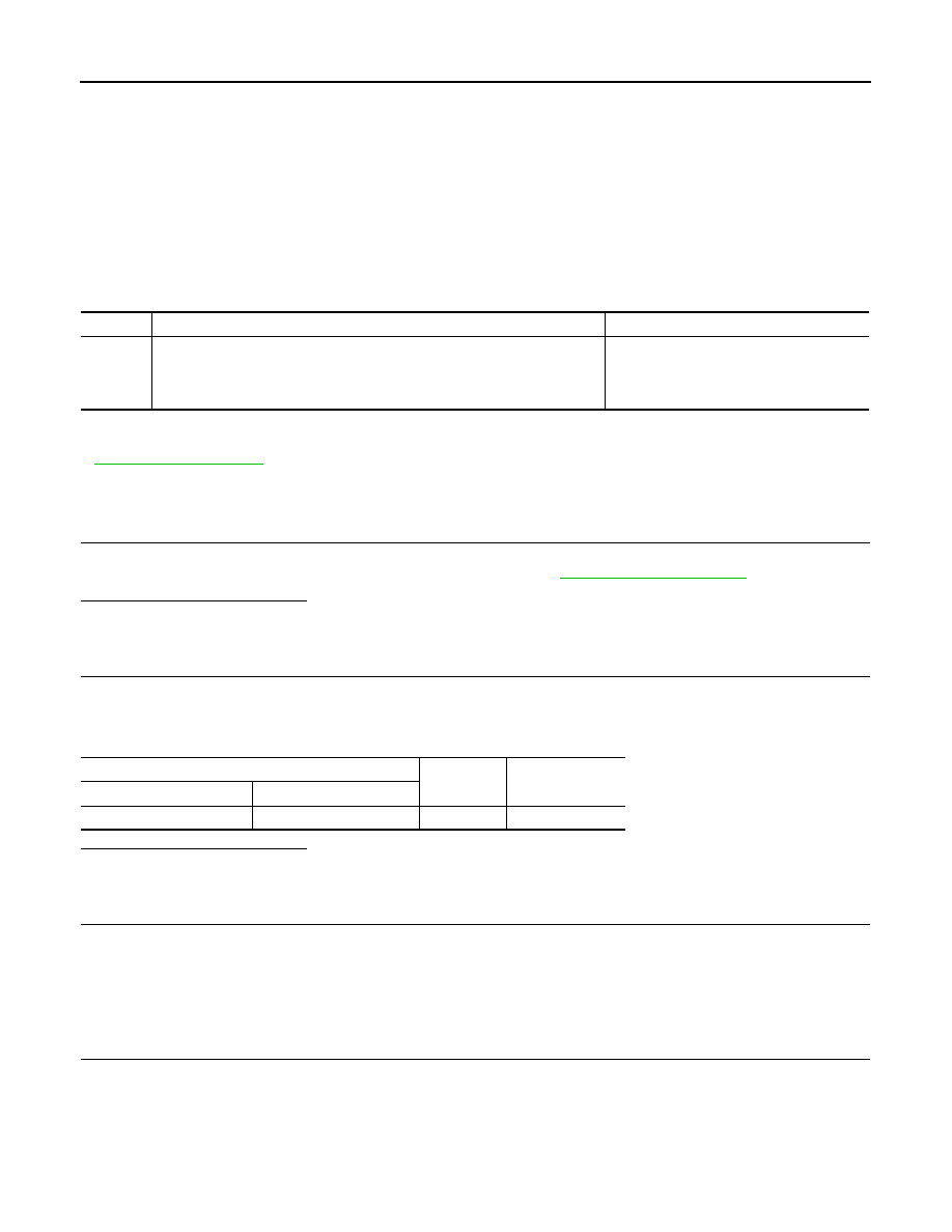
DTC No.
Trouble diagnosis name
Possible cause
P0530
REFRIGERANT PRESSURE SENSOR CIRCUIT
• CO.0: Short circuit to +12V or open circuit
• CC.1: Short circuit to ground
• Harness or connectors
(Refrigerant pressure sensor circuit is
open or shorted.)
• Refrigerant pressure sensor
Refrigerant pressure sensor
Ground
Voltage
Connector
Terminal
E17
3
Ground
Approx. 5V