содержание .. 584 585 586 587 ..
Nissan Tiida C11. Manual - part 586
EC-994
< ECU DIAGNOSIS >
[MR18DE]
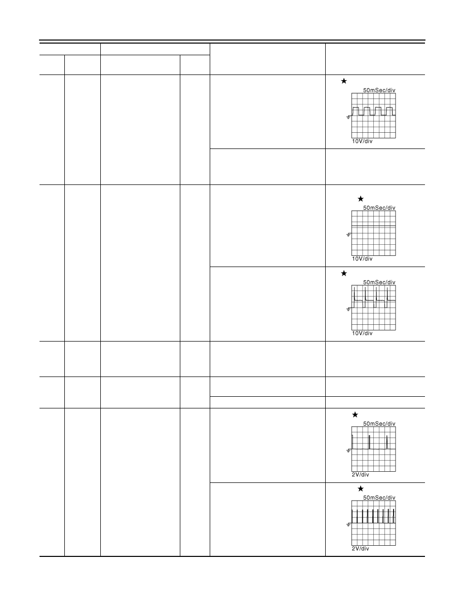
ECM
5
(G)
59
(O)
Heated oxygen sensor 2
heater
Output
[Engine is running]
• Engine speed: Below 3,600 rpm af-
ter the following conditions are met
- Engine: after warming up
- Keeping the engine speed between
3,500 and 4,000 rpm for 1 minute
and at idle for 1 minute under no
load
10V
[Ignition switch: ON]
• Engine stopped
[Engine is running]
• Engine speed: Above 3,600 rpm
BATTERY VOLTAGE
(11 - 14V)
9
(P)
108
(B)
EVAP canister purge vol-
ume control solenoid
valve
Output
[Engine is running]
• Idle speed
• Accelerator pedal: Not depressed
even slightly, after engine starting
BATTERY VOLTAGE
(11 - 14V)
[Engine is running]
• Engine speed: About 2,000 rpm
(More than 100 seconds after start-
ing engine.)
10V
10
(B)
11
(B)
—
ECM ground
—
—
—
15
(Y)
108
(B)
Throttle control motor re-
lay
Output
[Ignition switch: OFF]
BATTERY VOLTAGE
(11 - 14V)
[Ignition switch: ON]
0 - 1.0V
17
(R)
108
(B)
Ignition signal No. 1
Output
[Engine is running]
• Warm-up condition
• Idle speed
NOTE:
The pulse cycle changes depending
on rpm at idle
0 - 0.3V
18
(LG)
Ignition signal No. 2
21
(G)
Ignition signal No. 4
[Engine is running]
• Warm-up condition
• Engine speed: 2,000 rpm
0.2 - 0.5V
22
(SB)
Ignition signal No. 3
Terminal No.
Description
Condition
Value
(Approx.)
+
-–
Signal name
Input/
Output
JMBIA0325GB
JMBIA0327GB
JMBIA0328GB
JMBIA0329GB
JMBIA0330GB