Nissan Tiida C11. Manual - part 576


  Главная      Nissan     Nissan Tiida C11 - Service Manual


поиск по сайту            


содержание   ..  574  575  576  577   ..


Nissan Tiida C11. Manual - part 576


EC-954

< COMPONENT DIAGNOSIS >

[MR18DE]

P2127, P2128 APP SENSOR

7.

CHECK COMPONENTS

Check the following.
• Crankshaft position sensor (POS) (Refer to 

EC-865, "Component Inspection"

.)

• Refrigerant pressure sensor (Refer to 

EC-988, "Diagnosis Procedure"

.)

Is the inspection result normal?

YES

>> GO TO 14.

NO

>> Replace malfunctioning component.
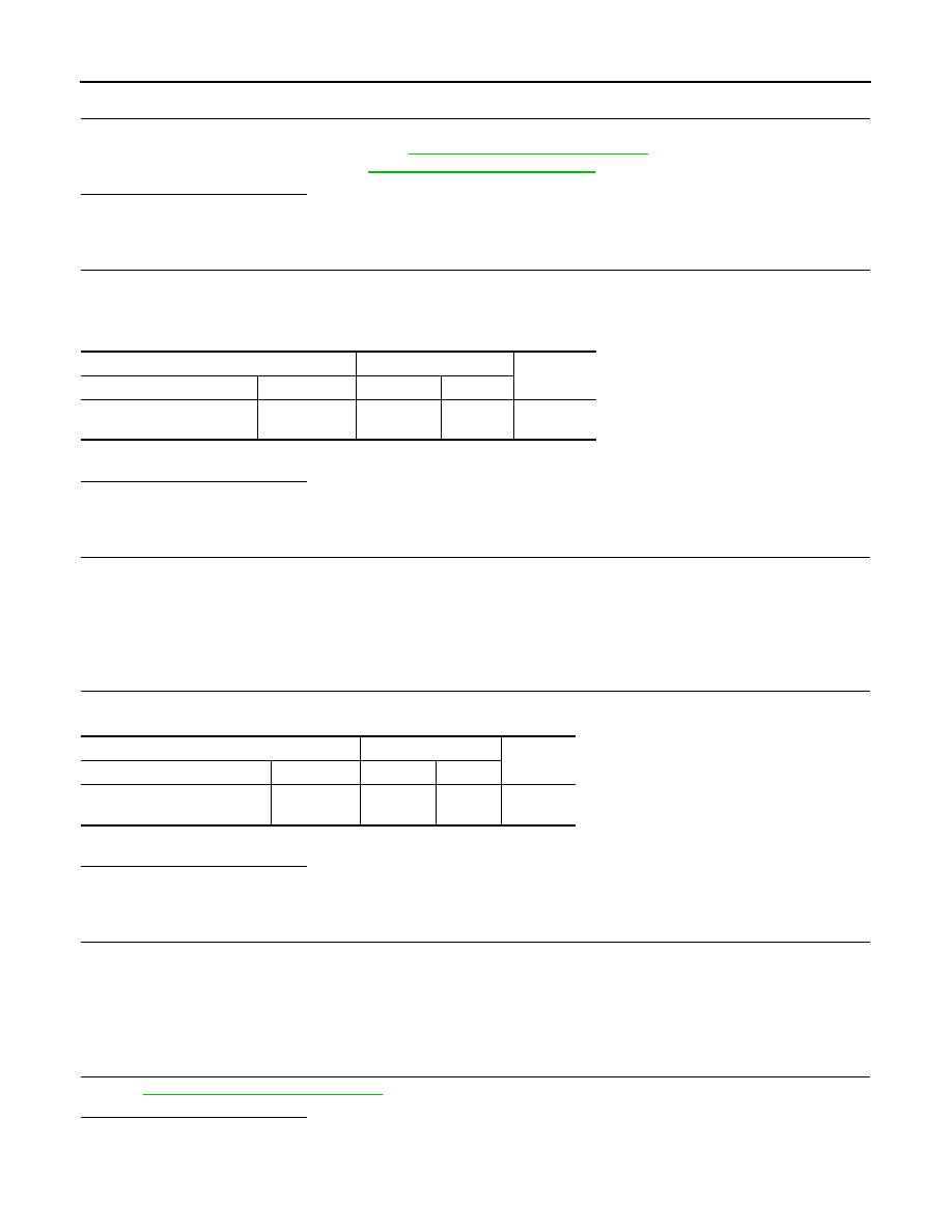
8.

CHECK APP SENSOR 2 GROUND CIRCUIT FOR OPEN AND SHORT

1.

Turn ignition switch OFF.

2.

Disconnect ECM harness connector.

3.

Check the continuity between APP sensor harness connector and ECM harness connector.

4.

Also check harness for short to ground and short to power.

Is the inspection result normal?

YES

>> GO TO 10.

NO

>> GO TO 9.

9.

DETECT MALFUNCTIONING PART

Check the following.
• Harness conector E7, M69, M25, M201 (RHD models)
• Harness for open or short between ECM and APP sensor

>> Repair open circuit or short to ground or short to power in harness or connectors.

10.

CHECK APP SENSOR 2 INPUT SIGNAL CIRCUIT FOR OPEN AND SHORT

1.

Check the continuity between APP sensor harness connector and ECM harness connector.

2.

Also check harness for short to ground and short to power.

Is the inspection result normal?

YES

>> GO TO 12.

NO

>> GO TO 11.

11.

DETECT MALFUNCTIONING PART

Check the following.
• Harness conector E7, M69, M25, M201 (RHD models)
• Harness for open or short between ECM and APP sensor

>> Repair open circuit or short to ground or short to power in harness or connectors.

12.

CHECK APP SENSOR

Refer to 

EC-955, "Component Inspection"

.

Is the inspection result normal?

YES

>> GO TO 10.

NO

>> GO TO 9.

APP sensor

ECM

Continuity

Connector

Terminal

Connector

Terminal

E12 (LHD models)

M204 (RHD models)

1

E16

104

Existed

APP sensor

ECM

Continuity

Connector

Terminal

Connector

Terminal

E12 (LHD models)

M204 (RHD models)

6

E16

103

Existed

P2127, P2128 APP SENSOR

EC-955

< COMPONENT DIAGNOSIS >

[MR18DE]

C

D

E

F

G

H

I

J

K

L

M

A

EC

N

P

O

13.

REPLACE ACCELERATOR PEDAL ASSEMBLY

1.

Replace accelerator pedal assembly.

2.

Go to 

EC-955, "Special Repair Requirement"

.

>> INSPECTION END

14.

CHECK INTERMITTENT INCIDENT

Refer to 

GI-55, "Intermittent Incident"

.

>> INSPECTION END

Component Inspection

INFOID:0000000001161941

1.

CHECK ACCELERATOR PEDAL POSITION SENSOR

1.

Reconnect all harness connectors disconnected.

2.

Turn ignition switch ON.

3.

Check the voltage between ECM harness connector and ground.

Is the inspection result normal?

YES

>> INSPECTION END

NO

>> GO TO 2.

2.

REPLACE ACCELERATOR PEDAL ASSEMBLY

1.

Replace accelerator pedal assembly.

2.

Go to 

EC-955, "Special Repair Requirement"

.

>> INSPECTION END

Special Repair Requirement

INFOID:0000000001161942

1.

PERFORM ACCELERATOR PEDAL RELEASED POSITION LEARNING

Refer to 

EC-693, "ACCELERATOR PEDAL RELEASED POSITION LEARNING : Special Repair Require-

ment"

.

>> GO TO 2.

2.

PERFORM THROTTLE VALVE CLOSED POSITION LEARNING

Refer to 

EC-694, "THROTTLE VALVE CLOSED POSITION LEARNING : Special Repair Requirement"

.

>> GO TO 3.

3.

PERFORM IDLE AIR VOLUME LEARNING

Refer to 

EC-694, "IDLE AIR VOLUME LEARNING : Special Repair Requirement"

.

>> END

(+)

(–)

Condition

Voltage

Connector

Terminal

Connector

Terminal

E16

110

(APP sensor 1 signal)

E16

111

Accelerator pedal

Fully released

0.6 - 0.9V

Fully depressed

3.9 - 4.7V

103

(APP sensor 2 signal)

104

Fully released

0.3 - 0.6V

Fully depressed

1.95 - 2.4V

EC-956

< COMPONENT DIAGNOSIS >

[MR18DE]

P2135 TP SENSOR

P2135 TP SENSOR

Description

INFOID:0000000001161943

Electric throttle control actuator consists of throttle control motor,
throttle position sensor, etc. The throttle position sensor responds to
the throttle valve movement. 
The throttle position sensor has two sensors. These sensors are a
kind of potentiometers which transform the throttle valve position into
output voltage, and emit the voltage signal to the ECM. In addition,
these sensors detect the opening and closing speed of the throttle
valve and feed the voltage signals to the ECM. The ECM judges the
current opening angle of the throttle valve from these signals and the
ECM controls the throttle control motor to make the throttle valve
opening angle properly in response to driving condition.

DTC Logic

INFOID:0000000001161944

DTC DETECTION LOGIC

NOTE:
If DTC P2135 is displayed with DTC P1229, first perform the trouble diagnosis for DTC P1229. Refer to

EC-928, "DTC Logic"

.

DTC CONFIRMATION PROCEDURE

1.

PRECONDITIONING

If DTC Confirmation Procedure has been previously conducted, always turn ignition switch OFF and wait at
least 10 seconds before conducting the next test.
TESTING CONDITION:
Before performing the following procedure, confirm that battery voltage is more than 8V at idle.

>> GO TO 2.

2.

PERFORM DTC CONFIRMATION PROCEDURE

1.

Start engine and let it idle for 1 second.

2.

Check DTC.

Is DTC detected?

YES

>> Go to 

EC-956, "Diagnosis Procedure"

.

NO

>> INSPECTION END

Diagnosis Procedure

INFOID:0000000001161945

1.

CHECK GROUND CONNECTION

1.

Turn ignition switch OFF.

2.

Check ground connection E15. Refer to Ground Inspection in 

GI-58, "Circuit Inspection"

.

Is the inspection result normal?

YES

>> GO TO 2.

NO

>> Repair or replace ground connection.

2.

CHECK THROTTLE POSITION SENSOR POWER SUPPLY CIRCUIT-I

1.

Disconnect electric throttle control actuator harness connector.

PBIB0145E

DTC No.

Trouble diagnosis name

DTC detecting condition

Possible cause

P2135

Throttle position sensor 
circuit range/perfor-
mance

Rationally incorrect voltage is sent to ECM 
compared with the signals from TP sensor 1 
and TP sensor 2.

• Harness or connector

(TP sensor 1 and 2 circuit is open or 
shorted.)

• Electric throttle control actuator

(TP sensor 1 and 2)

P2135 TP SENSOR

EC-957

< COMPONENT DIAGNOSIS >

[MR18DE]

C

D

E

F

G

H

I

J

K

L

M

A

EC

N

P

O

2.

Turn ignition switch ON.

3.

Check the voltage between electric throttle control actuator harness connector and ground.

Is the inspection result normal?

YES

>> GO TO 4.

NO

>> GO TO 3.

3.

CHECK THROTTLE POSITION SENSOR POWER SUPPLY CIRCUIT-II

1.

Turn ignition switch OFF.

2.

Disconnect ECM harness connector.

3.

Check the continuity between electric throttle control actuator harness connector and ground.

Is the inspection result normal?

YES

>> GO TO 4.

NO

>> Repair open circuit.

4.

CHECK THROTTLE POSITION SENSOR GROUND CIRCUIT FOR OPEN AND SHORT

1.

Turn ignition switch OFF.

2.

Disconnect ECM harness connector.

3.

Check the continuity between electric throttle control actuator harness connector and ground.

4.

Also check harness for short to ground and short to power.

Is the inspection result normal?

YES

>> GO TO 5.

NO

>> Repair open circuit or short to ground or short to power in harness or connectors.

5.

CHECK THROTTLE POSITION SENSOR INPUT SIGNAL CIRCUIT FOR OPEN AND SHORT

1.

Check the continuity between electric throttle control actuator harness connector and ground.

2.

Also check harness for short to ground and short to power.

Is the inspection result normal?

YES

>> GO TO 6.

NO

>> Repair open circuit or short to ground or short to power in harness or connectors.

6.

CHECK THROTTLE POSITION SENSOR

Refer to 

EC-958, "Component Inspection"

.

Is the inspection result normal?

YES

>> GO TO 8.

NO

>> GO TO 7.

Electric throttle control actuator

Ground

Voltage

Connector

Terminal

F7

2

Ground

Approx. 5V

Electric throttle control actuator

ECM

Continuity

Connector

Terminal

Connector

Terminal

F7

2

F11

72

Existed

Electric throttle control actuator

ECM

Continuity

Connector

Terminal

Connector

Terminal

F7

4

F11

36

Existed

Electric throttle control actuator

ECM

Continuity

Connector

Terminal

Connector

Terminal

F7

1

F11

33

Existed

3

34


содержание   ..  574  575  576  577   ..