Nissan Tiida C11. Manual - part 476


  Главная      Nissan     Nissan Tiida C11 - Service Manual


поиск по сайту            


содержание   ..  474  475  476  477   ..


Nissan Tiida C11. Manual - part 476


EC-554

< COMPONENT DIAGNOSIS >

[HR16DE (WITHOUT EURO-OBD)]

P1564 ASCD STEERING SWITCH

2.

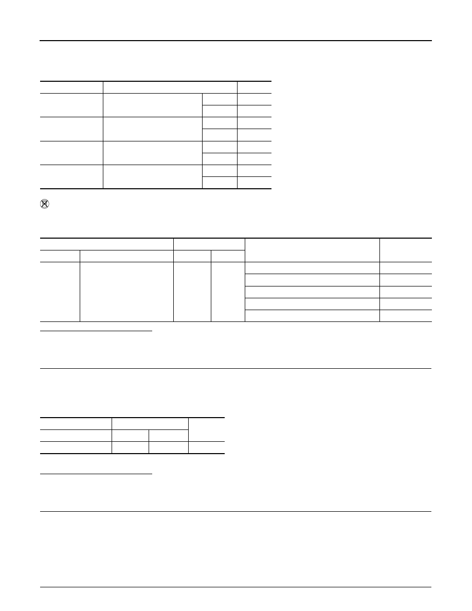
Select “MAIN SW”, “CANCEL SW”, “RESUME/ACC SW” and “SET SW” in “DATA MONITOR” mode with
CONSULT-III.

3.

Check each item indication under the following conditions.

 Without CONSULT-III

1.

Turn ignition switch ON.

2.

Check the voltage between ECM harness connector terminals as follows.

Is the inspection result normal?

YES

>> GO TO 8.

NO

>> GO TO 3.

3.

CHECK ASCD STEERING SWITCH GROUND CIRCUIT FOR OPEN AND SHORT

1.

Turn ignition switch OFF.

2.

Disconnect ECM harness connector.

3.

Disconnect combination switch harness connector M30.

4.

Check the continuity between combinarion switch and ECM harness connector.

5.

Also check harness for short to ground and short to power.

Is the inspection result normal?

YES

>> GO TO 5.

NO

>> GO TO 4.

4.

DETECT MALFUNCTIONING PART

Check the following.
• Harness connectors M69, E7
• Combination switch (spiral cable)
• Harness for open and short between ECM and combination switch

>> Repair open circuit or short to ground or short to power in harness or connectors.

5.

CHECK ASCD STEERING SWITCH INPUT SIGNAL CIRCUIT FOR OPEN AND SHORT

Monitor item

Condition

Indication

MAIN SW

MAIN switch

Pressed

ON

Released

OFF

CANCEL SW

CANCEL switch

Pressed

ON

Released

OFF

RESUME/ACC SW

RESUME/ACCELERATE switch

Pressed

ON

Released

OFF

SET SW

SET/COAST switch

Pressed

ON

Released

OFF

(+)

(–)

Condition

Voltage

Connector

Terminal

Connector

Terminal

E16

94

(ASCD steering switch signal)

E16

95

MAIN switch: Pressed

Approx. 0V

CANSEL switch: Pressed

Approx. 1V

SET/COAST switch: Pressed

Approx. 2V

RESUME/ACCELERATE switch: Pressed

Approx. 3V

All ASCD steering switches: Released

Approx. 4V

Combination switch

ECM

Continuity

Terminal

Connector

Terminal

15

E16

95

Existed

P1564 ASCD STEERING SWITCH

EC-555

< COMPONENT DIAGNOSIS >

[HR16DE (WITHOUT EURO-OBD)]

C

D

E

F

G

H

I

J

K

L

M

A

EC

N

P

O

1.

Check the continuity between ECM harness connector and combination switch.

2.

Also check harness for short to ground and short to power.

Is the inspection result normal?

YES

>> GO TO 7.

NO

>> GO TO 6.

6.

DETECT MALFUNCTIONING PART

Check the following.
• Harness connectors M69, E7
• Combination switch (spiral cable)
• Harness for open and short between ECM and combination switch

>> Repair open circuit or short to ground or short to power in harness or connectors.

7.

CHECK ASCD STEERING SWITCH

Refer to 

EC-555, "Component Inspection"

.

Is the inspection result normal?

YES

>> GO TO 8.

NO

>> Replace ASCD steering switch.

8.

CHECK INTERMITTENT INCIDENT

Refer to 

GI-55, "Intermittent Incident"

.

>> INSPECTION END

Component Inspection

INFOID:0000000001693378

1.

CHECK ASCD STEERING SWITCH

1.

Disconnect combination switch (spiral cable) harness connector.

2.

Check the continuity between combination switch harness connector terminals under following conditions.

Is the inspection result normal?

YES

>> INSPECTION END

NO

>> Replace ASCD steering switch

Combination switch

ECM

Continuity

Terminal

Connector

Terminal

14

E16

94

Existed

Combination meter

Condition

Resistance

Connector

Terminals

M30

14 and 15

MAIN switch: Pressed

Approx. 0 

CANCEL switch: Pressed

Approx. 250 

SET/COAST switch: Pressed

Approx. 660 

RESUME/ACCELERATE switch: Pressed

Approx. 1,480 

All ASCD steering switches: Released

Approx. 4,000 

EC-556

< COMPONENT DIAGNOSIS >

[HR16DE (WITHOUT EURO-OBD)]

P1572 ASCD BRAKE SWITCH

P1572 ASCD BRAKE SWITCH

Description

INFOID:0000000001693379

When the brake pedal is depressed, ASCD brake switch is turned OFF and stop lamp switch is turned ON.
ECM detects the state of the brake pedal by this input of two kinds (ON/OFF signal).
Refer to 

EC-424, "System Diagram"

 for the ASCD function.

DTC Logic

INFOID:0000000001693380

DTC DETECTION LOGIC

NOTE:
• If DTC P1572 is displayed with DTC P0605, first perform the trouble diagnosis for DTC P0605. Refer

to 

EC-524, "DTC Logic"

.

• This self-diagnosis has the one trip detection logic. When malfunction A is detected, DTC is not

stored in ECM memory. And in that case, 1st trip DTC and 1st trip freeze frame data are displayed.
1st trip DTC is erased when ignition switch OFF. And even when malfunction A is detected in two
consecutive trips, DTC is not stored in ECM memory.

DTC CONFIRMATION PROCEDURE

1.

INSPECTION START

Do you have CONSULT-III?.
Do you have CONSULT-III?

YES

>> GO TO 2.

NO

>> GO TO 5.

2.

PRECONDITIONING

If DTC Confirmation Procedure has been previously conducted, always turn ignition switch OFF and wait at
least 10 seconds before conducting the next test.
NOTE:
Procedure for malfunction B is not described here. It takes extremely long time to complete procedure for mal-
function B. By performing procedure for malfunction A, the incident that causes malfunction B can be
detected.

>> GO TO 3.

3.

PERFORM DTC CONFIRMATION PROCEDURE FOR MALFUNCTION A-I

With CONSULT-III

1.

Start engine.

2.

Select “DATA MONITOR” mode with CONSULT-III.

3.

Press MAIN switch and make sure that CRUISE indicator is displayed in combination meter.

4.

Drive the vehicle for at least 5 consecutive seconds under the following conditions.

CAUTION:

DTC No.

Trouble diagnosis 

name

DTC detecting condition

Possible cause

P1572

ASCD brake switch

A)

When the vehicle speed is above 30 km/h 
(19 MPH), ON signals from the stop lamp 
switch and the ASCD brake switch are sent 
to the ECM at the same time.

• Harness or connectors

(The stop lamp switch circuit is shorted.)

• Harness or connectors

(The ASCD brake switch circuit is shorted.)

• Harness or connectors

(The ASCD clutch switch circuit is shorted.)
(M/T)

• Stop lamp switch
• ASCD brake switch
• ASCD clutch switch (M/T)
• Incorrect stop lamp switch installation
• Incorrect ASCD brake switch installation
• Incorrect ASCD clutch switch installation (M/T)
• ECM

B)

ASCD brake switch signal is not sent to 
ECM for extremely long time while the ve-
hicle is driving.

P1572 ASCD BRAKE SWITCH

EC-557

< COMPONENT DIAGNOSIS >

[HR16DE (WITHOUT EURO-OBD)]

C

D

E

F

G

H

I

J

K

L

M

A

EC

N

P

O

Always drive vehicle at a safe speed.
NOTE:
This procedure may be conducted with the drive wheels lifted in the shop or by driving the vehicle.
If a road test is expected to be easier, it is unnecessary to lift the vehicle.

5.

Check 1st trip DTC.

Is 1st trip DTC detected?

YES

>> Go to 

EC-558, "Diagnosis Procedure"

.

NO

>> GO TO 4.

4.

PERFORM DTC CONFIRMATION PROCEDURE FOR MALFUNCTION A-II

With CONSULT-III

1.

Drive the vehicle for at least 5 consecutive seconds under the following conditions.

CAUTION:

Always drive vehicle at a safe speed.
NOTE:
This procedure may be conducted with the drive wheels lifted in the shop or by driving the vehicle.
If a road test is expected to be easier, it is unnecessary to lift the vehicle.

2.

Check 1st trip DTC.

Is 1st trip DTC detected?

YES

>> Go to 

EC-558, "Diagnosis Procedure"

.

NO

>> INSPECTION END

5.

PERFORM COMPONENT FUNCTION CHECK

Perform component check. Refer to 
Use component function check to check the overall function of the ASCD brake circuit. During this check, a 1st
trip DTC might not be confirmed.

Is the inspection result normal?

YES

>> INSPECTION END

NO

>> Go to 

EC-558, "Diagnosis Procedure"

.

Component Function Check

INFOID:0000000001705131

1.

PERFORM COMPONENT FUNCTION CHECK-I

Without CONSSULT-III

1.

Turn ignition switch ON.

2.

Check voltage between ECM harness connector and ground.

Is the inspection result normal?

YES

>> GO TO 2.

VHCL SPEED SE

More than 30 km/h (19 mph)

Shift lever

Suitable position 

VHCL SPEED SE

More than 30 km/h (19 mph)

Selector lever

Suitable position 

Driving location

Depress the brake pedal for more than 
five seconds so as not to come off from 
the above-mentioned vehicle speed.

(+)

(

)

Condition

Voltage

Connector

Terminal

Connector

Terminal

E16

100

(ASCD brake switch signal)

E16

108

Brake pedal and/or 
clutch pedal

Slightly depressed

Approx. 0V

Brake pedal and 
clutch pedal

Fully released

Battery voltage


содержание   ..  474  475  476  477   ..