Nissan Tiida C11. Manual - part 467


  Главная      Nissan     Nissan Tiida C11 - Service Manual


поиск по сайту            


содержание   ..  465  466  467  468   ..


Nissan Tiida C11. Manual - part 467


EC-518

< COMPONENT DIAGNOSIS >

[HR16DE (WITHOUT EURO-OBD)]

P0335 CKP SENSOR (POS)

Is the inspection result normal?

YES

>> GO TO 6.

NO

>> Replace refrigerant pressure sensor.

6.

CHECK APP SENSOR

Refer to 

EC-579, "Component Inspection"

.

Is the inspection result normal?

YES

>> GO TO 12.

NO

>> GO TO 7.

7.

REPLACE ACCELERATOR PEDAL ASSEMBLY

1.

Replace accelerator pedal assembly.

2.

Go to 

EC-389, "ACCELERATOR PEDAL RELEASED POSITION LEARNING : Special Repair Require-

ment"

.

>> INSPECTION END

8.

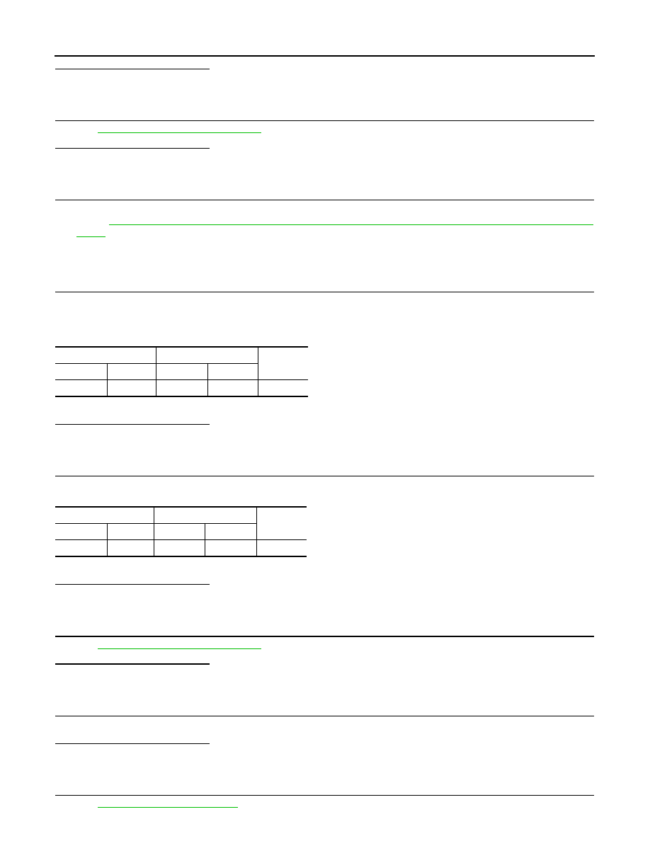
CHECK CKP SENSOR (POS) GROUND CIRCUIT FOR OPEN AND SHORT

1.

Turn ignition switch OFF.

2.

Disconnect ECM harness connector.

3.

Check the continuity between CKP sensor (POS) harness connector and ECM harness connector.

4.

Also check harness for short to ground and short to power.

Is the inspection result normal?

YES

>> GO TO 9.

NO

>> Repair open circuit or short to ground or short to power in harness or connectors.

9.

CHECK CKP SENSOR (POS) INPUT SIGNAL CIRCUIT FOR OPEN AND SHORT

1.

Check the continuity between CKP sensor (POS) harness connector and ECM harness connector.

2.

Also check harness for short to ground and short to power.

Is the inspection result normal?

YES

>> GO TO 10.

NO

>> Repair open circuit or short to ground or short to power in harness or connectors.

10.

CHECK CRANKSHAFT POSITION SENSOR (POS)

Refer to 

EC-519, "Component Inspection"

.

Is the inspection result normal?

YES

>> GO TO 11.

NO

>> Replace crankshaft position sensor (POS).

11.

CHECK GEAR TOOTH

Visually check for chipping signal plate gear tooth.
Is the inspection result normal?

YES

>> GO TO 12.

NO

>> Replace the signal plate.

12.

CHECK INTERMITTENT INCIDENT

Refer to 

GI-55, "Intermittent Incident"

.

CKP sensor (POS)

ECM

Continuity

Connector

Terminal

Connector

Terminal

F15

2

F11

62

Existed

CKP sensor (POS)

ECM

Continuity

Connector

Terminal

Connector

Terminal

F15

3

F11

61

Existed

P0335 CKP SENSOR (POS)

EC-519

< COMPONENT DIAGNOSIS >

[HR16DE (WITHOUT EURO-OBD)]

C

D

E

F

G

H

I

J

K

L

M

A

EC

N

P

O

>> INSPECTION END

Component Inspection

INFOID:0000000001693298

1.

CHECK CRANKSHAFT POSITION SENSOR (POS)-I

1.

Turn ignition switch OFF.

2.

Loosen the fixing bolt of the sensor.

3.

Disconnect crankshaft position sensor (POS) harness connector.

4.

Remove the sensor.

5.

Visually check the sensor for chipping.

Is the inspection result normal?

YES

>> GO TO 2.

NO

>> Replace crankshaft position sensor (POS).

2.

CHECK CRANKSHAFT POSITION SENSOR (POS)-II

Check resistance between crankshaft position sensor (POS) terminals as follows.

Is the inspection result normal?

YES

>> INSPECTION END

NO

>> Replace crankshaft position sensor (POS).

PBIA9209J

Terminals (Polarity)

Resistance [at 25

°

C (77

°

F)]

1 (+) - 2 (-)

Except 0 or 


1 (+) - 3 (-)

2 (+) - 3 (-)

EC-520

< COMPONENT DIAGNOSIS >

[HR16DE (WITHOUT EURO-OBD)]

P0340 CMP SENSOR (PHASE)

P0340 CMP SENSOR (PHASE)

Description

INFOID:0000000001693299

The camshaft position sensor (PHASE) senses the retraction of
camshaft (INT) to identify a particular cylinder. The camshaft position
sensor (PHASE) senses the piston position.
When the crankshaft position sensor (POS) system becomes inoper-
ative, the camshaft position sensor (PHASE) provides various con-
trols of engine parts instead, utilizing timing of cylinder identification
signals.
The sensor consists of a permanent magnet and Hall IC.
When engine is running, the high and low parts of the teeth cause
the gap with the sensor to change.
The changing gap causes the magnetic field near the sensor to
change.
Due to the changing magnetic field, the voltage from the sensor changes. 
ECM receives the signals as shown in the figure.

DTC Logic

INFOID:0000000001693300

DTC DETECTION LOGIC

NOTE:
If DTC P0340 is displayed with DTC P1129, first perform the trouble diagnosis for DTC P1129. Refer to

EC-551, "DTC Logic"

.

DTC CONFIRMATION PROCEDURE

1.

PRECONDITIONING

If DTC Confirmation Procedure has been previously conducted, always turn ignition switch OFF and wait at
least 10 seconds before conducting the next test.
TESTING CONDITION:
Before performing the following procedure, confirm that battery voltage is more than 10.5V with igni-
tion switch ON.

>> GO TO 2.

2.

PERFORM DTC CONFIRMATION PROCEDURE-I

1.

Start engine and let it idle for at least 5 seconds.
If engine does not start, crank engine for at least 2 seconds.

2.

Check 1st trip DTC.

PBIA9875J

JMBIA0714GB

DTC No.

Trouble diagnosis name

DTC detecting condition

Possible cause

P0340

Camshaft position sen-
sor (PHASE) circuit

• The cylinder No. signal is not sent to ECM for 

the first few seconds during engine cranking.

• The cylinder No. signal is not sent to ECM 

during engine running.

• The cylinder No. signal is not in the normal 

pattern during engine running.

• Harness or connectors

(The sensor circuit is open or shorted)

• Camshaft position sensor (PHASE)
• Camshaft (INT)
• Starter motor
• Starting system circuit
• Dead (Weak) battery

P0340 CMP SENSOR (PHASE)

EC-521

< COMPONENT DIAGNOSIS >

[HR16DE (WITHOUT EURO-OBD)]

C

D

E

F

G

H

I

J

K

L

M

A

EC

N

P

O

Is 1st trip DTC detected?

YES

>> Go to 

EC-521, "Diagnosis Procedure"

.

NO

>> GO TO 3.

3.

PERFORM DTC CONFIRMATION PROCEDURE-I

1.

Maintaining engine speed at more than 800 rpm for at least 5 seconds.

2.

Check 1st trip DTC.

Is 1st trip DTC detected?

YES

>> Go to 

EC-521, "Diagnosis Procedure"

.

NO

>> INSPECTION END

Diagnosis Procedure

INFOID:0000000001693301

1.

CHECK STARTING SYSTEM

Turn ignition switch to START position.

Does the engine turn over? Does the starter motor operate?

YES

>> GO TO 2.

NO

>> Check starting system.

2.

CHECK GROUND CONNECTION

1.

Turn ignition switch OFF.

2.

Check ground connection E15. Refer to Ground Inspection in 

GI-58, "Circuit Inspection"

.

Is the inspection result normal?

YES

>> GO TO 3.

NO

>> Repair or replace ground connection.

3.

CHECK CAMSHAFT POSITION (CMP) SENSOR (PHASE) POWER SUPPLY CIRCUIT

1.

Disconnect camshaft position (CMP) sensor (PHASE) harness connector.

2.

Turn ignition switch ON.

3.

Check the voltage between CMP sensor (PHASE) harness connector and ground.

Is the inspection result normal?

YES

>> GO TO 4.

NO

>> Repair open circuit or short to ground or short to power in harness or connectors.

4.

CHECK CMP SENSOR (PHASE) GROUND CIRCUIT FOR OPEN AND SHORT

1.

Turn ignition switch OFF.

2.

Disconnect ECM harness connector.

3.

Check the continuity between CMP sensor (PHASE) harness connector and ECM harness connector.

4.

Also check harness for short to ground and short to power.

Is the inspection result normal?

YES

>> GO TO 5.

NO

>> Repair open circuit or short to ground or short to power in harness or connectors.

5.

CHECK CMP SENSOR (PHASE) INPUT SIGNAL CIRCUIT FOR OPEN AND SHORT

1.

Check the continuity between CMP sensor (PHASE) harness connector and ECM harness connector.

CMP sensor (PHASE)

Ground

Voltage

Connector

Terminal

F21

1

Ground

Approx. 5V

CMP sensor (PHASE)

ECM

Continuity

Connector

Terminal

Connector

Terminal

F21

2

F11

63

Existed


содержание   ..  465  466  467  468   ..