Nissan Tiida C11. Manual - part 463


  Главная      Nissan     Nissan Tiida C11 - Service Manual


поиск по сайту            


содержание   ..  461  462  463  464   ..


Nissan Tiida C11. Manual - part 463


EC-502

< COMPONENT DIAGNOSIS >

[HR16DE (WITHOUT EURO-OBD)]

P0134 HO2S1

P0134 HO2S1

Description

INFOID:0000000001693259

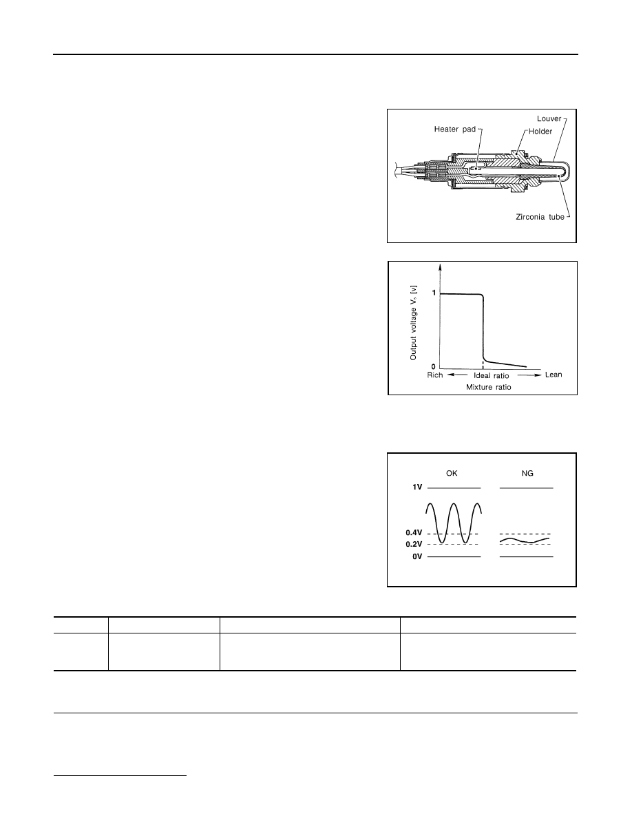
The heated oxygen sensor 1 is placed into the exhaust manifold. It
detects the amount of oxygen in the exhaust gas compared to the
outside air. The heated oxygen sensor 1 has a closed-end tube
made of ceramic zirconia. The zirconia generates voltage from
approximately 1V in richer conditions to 0V in leaner conditions. The
heated oxygen sensor 1 signal is sent to the ECM. The ECM adjusts
the injection pulse duration to achieve the ideal air-fuel ratio. The
ideal air-fuel ratio occurs near the radical change from 1V to 0V.

DTC Logic

INFOID:0000000001693260

DTC DETECTION LOGIC

Under the condition in which the heated oxygen sensor 1 signal is
not input, the ECM circuits will read a continuous approximately
0.3V. Therefore, for this diagnosis, the time that output voltage is
within 200 to 400 mV range is monitored, and the diagnosis checks
that this time is not inordinately long.

DTC CONFIRMATION PROCEDURE

1.

PRECONDITIONING

If DTC Confirmation Procedure has been previously conducted, always turn ignition switch OFF and wait at
least 10 seconds before conducting the next test.
TESTING CONDITION:
Before performing the following procedure, confirm that battery voltage is more than 11V at idle.

Do you have CONSULT-III?

SEF463R

SEF288D

SEF237U

DTC No.

Trouble diagnosis name

DTC detecting condition

Possible cause

P0134
0134

Heated oxygen sensor 1 
circuit no activity detected

The voltage from the sensor is constantly ap-
prox. 0.3V.

• Harness or connectors

(The sensor circuit is open or shorted.)

• Heated oxygen sensor 1

P0134 HO2S1

EC-503

< COMPONENT DIAGNOSIS >

[HR16DE (WITHOUT EURO-OBD)]

C

D

E

F

G

H

I

J

K

L

M

A

EC

N

P

O

YES

>> GO TO 2.

NO

>> GO TO 3.

2.

PERFORM DTC CONFIRMATION PROCEDURE-I

With CONSULT-III

1.

Start engine and warm it up to normal operating temperature.

2.

Stop engine and wait at least 10 seconds.

3.

Turn ignition switch ON and select “HO2S1 (B1) P0134” of “HO2S1” in “DTC WORK SUPPORT” mode
with CONSULT-III.

4.

Touch “START”.

5.

Start engine and let it idle for at least 3 minutes.
NOTE:
Never raise engine speed above 3,600 rpm after this step. If the engine speed limit is exceeded,
return to step 5.

6.

When the following conditions are met, “TESTING” will be displayed on the CONSULT-III screen. Maintain
the conditions continuously until “TESTING” changes to “COMPLETED”. (It will take approximately 40 to
50 seconds.)

CAUTION:

Always drive vehicle at a safe speed.

If “TESTING” is not displayed after 5 minutes, retry from step 2.

7.

Touch “SELF-DIAG RESULTS”.

Which displayed on COUSULT-III screen?

OK

>> INSPECTION END.

NG

>> Go to 

EC-503, "Diagnosis Procedure"

.

3.

PERFORM COMPONENT FUNCTION CHECK

 Without CONSULT-III

1.

Start engine and warm it up to normal operating temperature.

2.

Set voltmeter probes between ECM harness connector terminals as follows.

Is the inspection result normal?

YES

>> INSPECTION END.

NO

>> Go to 

EC-503, "Diagnosis Procedure"

.

Diagnosis Procedure

INFOID:0000000001693261

1.

CHECK GROUND CONNECTION

1.

Turn ignition switch OFF.

2.

Check ground connection E15. Refer to Ground Inspection in 

GI-58, "Circuit Inspection"

.

Is the inspection result normal?

YES

>> GO TO 2

NO

>> Repair or replace ground connection.

2.

CHECK HO2S1 GROUND CIRCUIT FOR OPEN AND SHORT

1.

Disconnect heated oxygen sensor 1 harness connector.

ENG SPEED

1,300 - 3,500 rpm

VHCL SPEED SE

More than 80 km/h (50 MPH)

B/FUEL SCHDL

3 - 15 msec

Shift lever

Suitable position

(+)

(–)

Condition

Voltage

Connector

Terminal

Connector

Terminal

F11

49

(HO2S1 signal)

F11

56

Engine speed held at 

2,000 rpm constant under 

no load.

• The voltage dose not remain in the range of 

0.2 to 0.4.

EC-504

< COMPONENT DIAGNOSIS >

[HR16DE (WITHOUT EURO-OBD)]

P0134 HO2S1

2.

Disconnect ECM harness connector.

3.

Check harness continuity between ECM harness connector and HO2S1 harness connector.

4.

Also check harness for short to ground and short to power.

Is the inspection result normal?

YES

>> GO TO 3.

NO

>> Repair open circuit or short to ground or short to power in harness or connectors.

3.

CHECK HO2S1 INPUT SIGNAL CIRCUIT FOR OPEN AND SHORT

1.

Check harness continuity between HO2S1 harness connector and ECM harness connector.

2.

Check harness continuity between ECM harness connector or HO2S1 harness connector and ground.

3.

Also check harness for short to power.

Is the inspection result normal?

YES

>> GO TO 4.

NO

>> Repair open circuit or short to ground or short to power in harness or connectors.

4.

CHECK HEATED OXYGEN SENSOR 1

Refer to 

EC-504, "Component Inspection"

.

Is the inspection result normal?

YES

>> GO TO 5.

NO

>> Replace heated oxygen sensor 1.

5.

CHECK INTERMITTENT INCIDENT

Refer to 

GI-55, "Intermittent Incident"

.

>> INSPECTION END

Component Inspection

INFOID:0000000001693262

1.

INSPECTION START

Do you have CONSULT-III?

Do you have CONSULT-III?

YES

>> GO TO 2.

NO

>> GO TO 3.

2.

CHECK HEATED OXYGEN SENSOR 1

 With CONSULT-III

1.

Start engine and warm it up to normal operating temperature.

2.

Set “POST TRIGGER” to 100% in “DATA MONITOR” mode with CONSULT-III. 

3.

Select “HO2S1 (B1)” and “HO2S1 MNTR (B1)”.

4.

Hold engine speed at 2,000 rpm under no load during the following steps.

5.

Touch “RECORD” on CONSULT-III screen.

HO2S1

ECM

Continuity

Connector

Terminal

Connector

Terminal

F12

1

F11

56

Existed

HO2S1

ECM

Continuity

Connector

Terminal

Connector

Terminal

F12

4

F11

49

Existed

HO2S1

ECM

Ground

Continuity

Connector

Terminal

Connector

Terminal

F12

4

F11

49

Ground

Not existed

P0134 HO2S1

EC-505

< COMPONENT DIAGNOSIS >

[HR16DE (WITHOUT EURO-OBD)]

C

D

E

F

G

H

I

J

K

L

M

A

EC

N

P

O

6.

Check the following.

-

“HO2S1 MNTR (B1)” in “DATA MONITOR” mode changes from
“RICH” to “LEAN” to “RICH” more than 5 times in 10 seconds.

5 times (cycles) are counted as shown in the figure.

-

“HO2S1 (B1)” voltage goes above 0.6V at least once.

-

“HO2S1 (B1)” voltage goes below 0.3V at least once.

-

“HO2S1 (B1)” voltage never exceeds 1.0V.

CAUTION:

Discard any heated oxygen sensor which has been dropped from a height of more than 0.5 m
(19.7 in) onto a hard surface such as a concrete floor; use a new one.

Before installing new oxygen sensor, clean exhaust system threads using Oxygen Sensor
Thread Cleaner tool and approved anti-seize lubricant.

Is the inspection result normal?

YES

>> INSPECTION END

NO

>> GO TO 3.

3.

CHECK HEATED OXYGEN SENSOR 1

 Without CONSULT-III

1.

Start engine and warm it up to normal operating temperature.

2.

Check the voltage between ECM harness connector terminals as follows under the following condition.

CAUTION:

• Discard any heated oxygen sensor which has been dropped from a height of more than 0.5 m (19.7

in) onto a hard surface such as a concrete floor; use a new one.

• Before installing new oxygen sensor, clean exhaust system threads using Oxygen Sensor Thread

Cleaner tool and approved anti-seize lubricant.

Is the inspection result normal?

YES

>> INSPECTION END

NO

>> GO TO 4

4.

REPLACE HEATED OXYGEN SENSOR 1

Replace heated oxygen sensor 1.

CAUTION:

SEF217YA

JMBIA0352ZZ

(+)

(–)

Condition

Voltage

Connector

Terminal

Connector

Terminal

F11

49

(HO2S1 signal)

E11

56

Engine speed held 
at 2,000 rpm con-
stant under no 
load.

• The voltage fluctuates between 0 to 0.3V and 0.6 to 

1.0V more than 5 times within 10 seconds.

• The maximum voltage is over 0.6V at least 1 time.
• The minimum voltage is below 0.3V at least 1 time.
• The voltage never exceeds 1.0V.
1 time: 0 - 0.3V 

 0.6 - 1.0V 

 0 - 0.3V

2 times: 0 - 0.3V 

 0.6 - 1.0V 

 0 - 0.3V 

 0.6 - 1.0V 

 0 - 0.3V


содержание   ..  461  462  463  464   ..