содержание .. 449 450 451 452 ..
Nissan Tiida C11. Manual - part 451
EC-454
< FUNCTION DIAGNOSIS >
[HR16DE (WITHOUT EURO-OBD)]
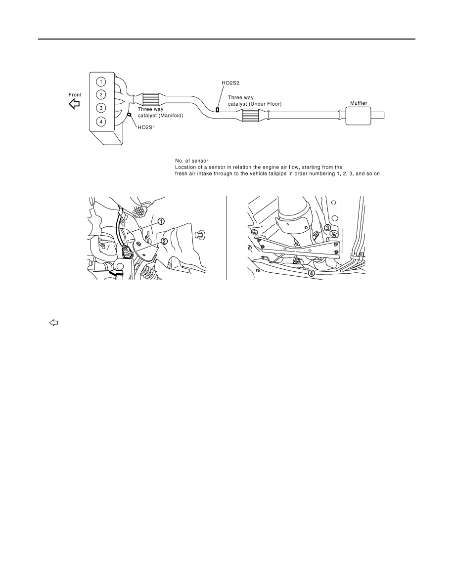
INTAKE VALVE TIMING CONTROL
1.
Exhaust manifold
2.
Heated oxygen sensor 1
3.
Heated oxygen sensor 2
4.
Heated oxygen sensor 2 harness
connector
Vehicle front
PBIB2942E
PBIB2943E