содержание .. 443 444 445 446 ..
Nissan Tiida C11. Manual - part 445
EC-430
< FUNCTION DIAGNOSIS >
[HR16DE (WITHOUT EURO-OBD)]
AUTOMATIC SPEED CONTROL DEVICE (ASCD)
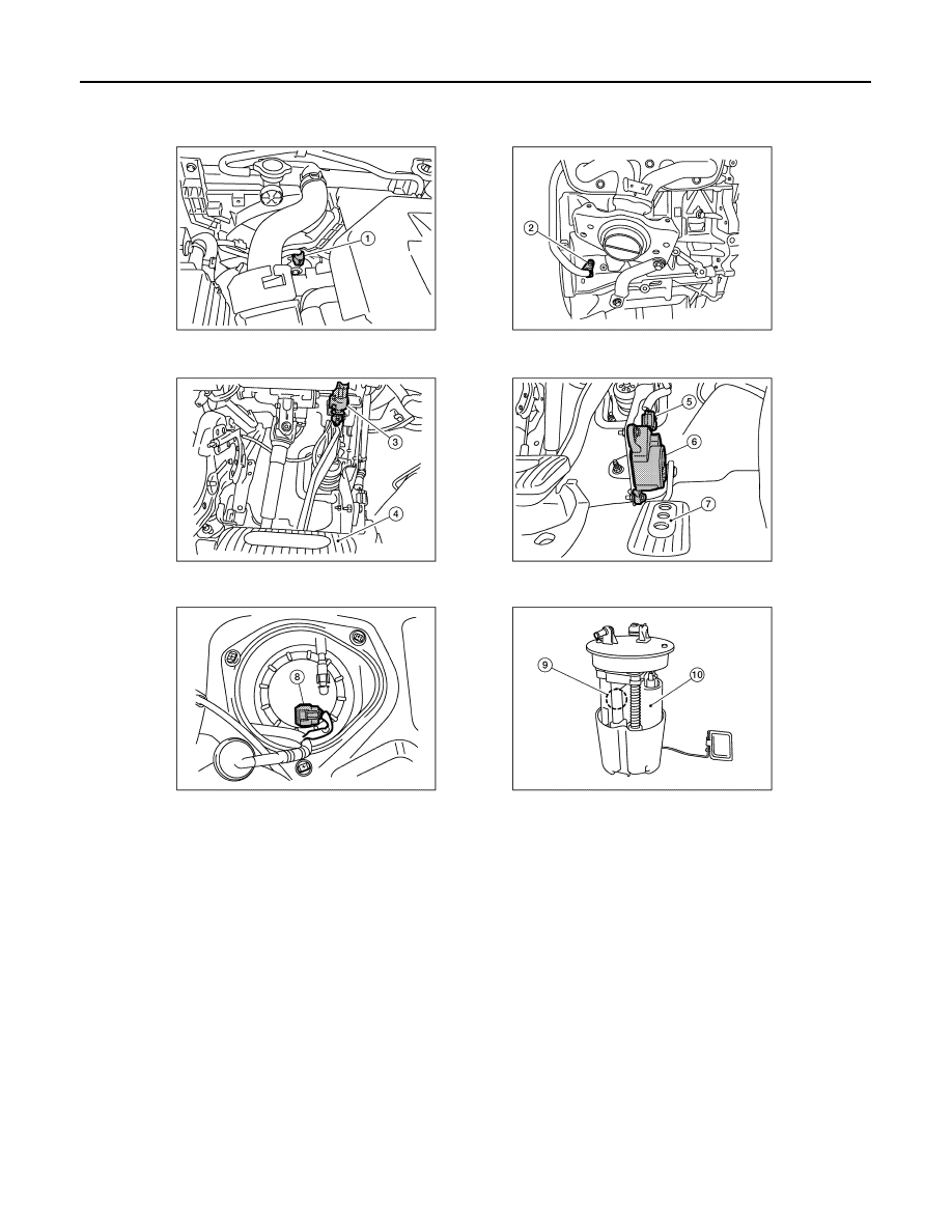
1.
Cooling fan motor harness connec-
tor
2.
Crankshaft position sensor
3.
Stop lamp switch
4.
Brake pedal
5.
Accelerator pedal position sensor
harness connector
6.
Accelerator pedal position sensor
7.
Accelerator pedal
8.
Fuel level sensor unit and fuel pump
harness connector (view with in-
spection hole cover removed)
9.
Fuel pressure regulator
10. Fuel pump
AWBIA0044ZZ