содержание .. 388 389 390 391 ..
Nissan Tiida C11. Manual - part 390
EC-210
< COMPONENT DIAGNOSIS >
[HR16DE (WITH EURO-OBD)]
P0444 EVAP CANISTER PURGE VOLUME CONTROL SOLENOID VALVE
P0444 EVAP CANISTER PURGE VOLUME CONTROL SOLENOID VALVE
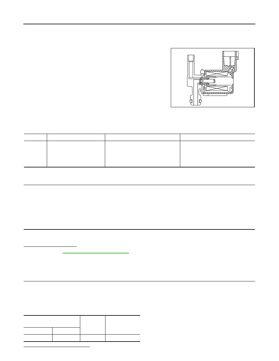
Description
INFOID:0000000001670971
The EVAP canister purge volume control solenoid valve uses a ON/
OFF duty to control the flow rate of fuel vapor from the EVAP canis-
ter. The EVAP canister purge volume control solenoid valve is
moved by ON/OFF pulses from the ECM. The longer the ON pulse,
the greater the amount of fuel vapor that will flow through the valve.
DTC Logic
INFOID:0000000001670972
DTC DETECTION LOGIC
DTC CONFIRMATION PROCEDURE
1.
CONDITIONING
If DTC Confirmation Procedure has been previously conducted, always turn ignition switch OFF and wait at
least 10 seconds before conducting the next test.
TESTING CONDITION:
Before performing the following procedure, confirm battery voltage is more than 11V at idle.
>> GO TO 2.
2.
PERFORM DTC CONFIRMATION PROCEDURE
1.
Start engine and let it idle for at least 13 seconds.
2.
Check 1st trip DTC.
Is 1st trip DTC detected?
YES
>> Go to
NO
>> INSPECTION END
Diagnosis Procedure
INFOID:0000000001670973
1.
CHECK EVAP CANISTER PURGE VOLUME CONTROL SOLENOID VALVE POWER SUPPLY CIRCUIT
1.
Turn ignition switch OFF.
2.
Disconnect EVAP canister purge volume control solenoid valve harness connector.
3.
Turn ignition switch ON.
4.
Check the voltage between EVAP canister purge volume control solenoid valve harness connector and
ground.
Is the inspection result normal?
PBIA9215J
DTC No.
Trouble diagnosis name
DTC detecting condition
Possible cause
P0444
EVAP canister purge volume
control solenoid valve circuit
open
An excessively low voltage signal is sent
to ECM through the valve
• Harness or connectors
(The solenoid valve circuit is open or
shorted.)
• EVAP canister purge volume control so-
lenoid valve
EVAP canister purge volume
control solenoid valve
Ground
Voltage
Connector
Terminal
F22
1
Ground
Battery voltage