содержание .. 340 341 342 343 ..
Nissan Tiida C11. Manual - part 342
EC-18
< BASIC INSPECTION >
[HR16DE (WITH EURO-OBD)]
DIAGNOSIS AND REPAIR WORKFLOW
BASIC INSPECTION
DIAGNOSIS AND REPAIR WORKFLOW
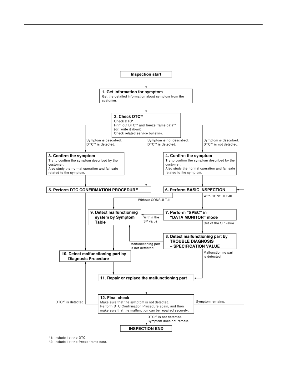
Work Flow
INFOID:0000000001161121
OVERALL SEQUENCE
DETAILED FLOW
JMBIA0078GB