Nissan Tiida C11. Manual - part 238


  Главная      Nissan     Nissan Tiida C11 - Service Manual


поиск по сайту            


содержание   ..  236  237  238  239   ..


Nissan Tiida C11. Manual - part 238


DLK-362

< COMPONENT DIAGNOSIS >

[WITH I-KEY & SUPER LOCK]

OUTSIDE KEY ANTENNA

OUTSIDE KEY ANTENNA

Description

INFOID:0000000001530358

Detects whether the Intelligent Key is in the operating range of the outside antennas.
Front outside antennas are integrated in front outside door handles (driver side, passenger side) to allow lock-
ing and unlocking of door locks including back door (hatchback) and trunk lid (sedan) when the Intelligent Key
is present.
Rear bumper antenna is mounted on the rear bumper and is used to allow the locking and unlocking of door
locks including back door (hatchback) and trunk lid (sedan) when the Intelligent Key is present.

Component Function Check

INFOID:0000000001530359

1.

CHECK DOOR REQUEST SWITCH

Check that door request switches operate normally.

Is the inspection result normal?

YES

>> GO TO 2.

NO

>> Inspect door request switches. Refer to 

XX-XX, "*****"

.

2.

CHECK FRONT ANTENNAS FUNCTION

Be sure that Intelligent Key is in each outside key antenna detection range.

Does door lock/unlock when each request switch is pressed?

YES

>> Outside key antenna is OK.

NO

>> Refer to 

DLK-362, "Diagnosis Procedure"

.

Diagnosis Procedure

INFOID:0000000001530360

1.

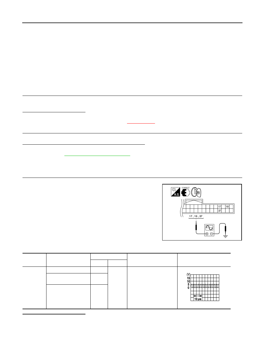
CHECK OUTSIDE KEY ANTENNA INPUT SIGNAL

1.

Turn ignition switch OFF.

2.

Check signal between Intelligent Key unit connector M52 termi-
nals 17, 19, 37 and ground with an oscilloscope.

Is the inspection result normal?

YES

>> Outside key antenna is OK.

NO

>> GO TO 2.

WIIA1198E

Connector

Item

Terminals

Condition

Signal

(Reference value)

(+)

(-)

M52

Rear bumper antenna

17

Ground

Request switch is pushed

Front outside antenna 
(driver side)

19

Front outside antenna 
(passenger side)

37

SIIA1910J

OUTSIDE KEY ANTENNA

DLK-363

< COMPONENT DIAGNOSIS >

[WITH I-KEY & SUPER LOCK]

C

D

E

F

G

H

I

J

L

M

A

B

DLK

N

O

P

2.

CHECK OUTSIDE KEY ANTENNA CIRCUIT

1.

Disconnect Intelligent Key unit connector and outside key antenna connector.

2.

Check continuity between each outside key antenna harness
connector (B) D10 (driver side) or D106 (passenger side), rear
bumper antenna connector (C) B81 terminals 1, 2 and Intelligent
Key unit harness connector (A) M52 terminals 17, 18, 19, 20,
37, and 38.

3.

Check continuity between each outside key antenna harness
connector terminals 1, 2 and ground.

Is the inspection result normal?

YES

>> GO TO 3.

NO

>> Repair or replace harness between outside key antenna and Intelligent Key unit.

3.

CHECK OUTSIDE KEY ANTENNA POWER SUPPLY

1.

Replace outside key antenna. (New antenna or other antenna)

2.

Connect Intelligent Key unit connector and outside key antenna connector.

3.

Check signal between Intelligent Key unit connector terminals
17, 19, 37 and ground with an oscilloscope.

Is the inspection result normal?

YES

>> Replace outside key antenna.

NO

>> Replace Intelligent Key unit. Refer to 

XX-XX, "*****"

.

Item

Connector

Terminal

Connector

Terminal

Continuity

Rear bumper antenna

C: B81

1

A: M52

17

Yes

2

18

Front outside antenna 

(driver side)

B: D10

1

19

2

20

Front outside antenna 

(passenger side)

B: D106

1

37

2

38

Item

Connector

Terminal

Continuity

Rear bumper antenna

C: B81

1

Ground

No

2

Front outside antenna 

(driver side)

B: D10

1

2

Front outside antenna 

(passenger side)

B: D106

1

2

WIIA1199E

Connector

Item

Terminals

Condition

Signal

(Reference value)

(+)

(-)

M52

Rear 
bumper

17

Ground

Request 
switch is 
pushed

Driver 
side

19

Pas-
senger 
side

37

WIIA1198E

SIIA1910J

DLK-364

< COMPONENT DIAGNOSIS >

[WITH I-KEY & SUPER LOCK]

STEERING LOCK SOLENOID

STEERING LOCK SOLENOID

Diagnosis Procedure

INFOID:0000000001530365

1.

CHECK STEERING LOCK SOLENOID POWER SUPPLY

1.

Turn ignition switch OFF.

2.

Disconnect steering lock solenoid connector.

3.

Check voltage between steering lock solenoid and ground.

Is the inspection result normal?

YES

>> GO TO 2.

NO

>> Repair or replace steering lock solenoid power supply

circuit.

2.

CHECK STEERING LOCK SOLENOID GROUND CIRCUIT

Check continuity between steering lock solenoid and ground.

Is the inspection result normal?

YES

>> GO TO 3.

NO

>> GO TO 6.

3.

CHECK INTELLIGENT KEY UNIT OUTPUT SIGNAL

1.

Connect steering lock solenoid connector.

2.

Check voltage between Intelligent Key unit and ground.

Is the inspection result normal?

YES

>> GO TO 4.

NO

>> Replace Intelligent Key unit. Refer to 

SEC-79, "Removal

and Installation"

.

4.

CHECK STEERING LOCK COMMUNICATION SIGNAL

Check signal between Intelligent Key unit and ground with oscilloscope.

Terminals

Voltage (V)

(Approx.)

(+)

(–)

Steering lock sole-

noid

Terminal

M6

1

Ground

Battery voltage

PIIB6632E

Steering lock solenoid connector

Terminal

Ground

Continuity 

M6

4

Yes

PIIB6633E

Terminals

Voltage (V)

(Approx.)

(+)

(–)

Intelligent Key unit 

connector

Terminal

M52

1

Ground

5

PIIB6634E

STEERING LOCK SOLENOID

DLK-365

< COMPONENT DIAGNOSIS >

[WITH I-KEY & SUPER LOCK]

C

D

E

F

G

H

I

J

L

M

A

B

DLK

N

O

P

Is the inspection result normal?

YES

>> GO TO 5.

NO

>> Replace Intelligent Key unit. Refer to 

SEC-79, "Removal and Installation"

.

5.

CHECK STEERING LOCK SOLENOID COMMUNICATION CIRCUIT

1.

Disconnect Intelligent Key unit and steering lock solenoid connectors.

2.

Check continuity between Intelligent Key unit and steering lock solenoid.

3.

Check continuity between steering lock solenoid and ground.

Is the inspection result normal?

YES

>> Replace steering lock solenoid.

NO

>> Repair or replace harness between steering lock solenoid and Intelligent Key unit.

6.

CHECK STEERING LOCK SOLENOID GROUND CIRCUIT

1.

Disconnect Intelligent Key unit connector.

2.

Check continuity between Intelligent Key unit and steering lock solenoid.

Terminals

Condition of 

key switch

Voltage (V)

(Approx.)

(+)

(–)

Intelligent 

Key unit 

connector

Terminal

M52

32

Ground

Ignition 

switch is 
pressed, 

when Intelli-

gent Key is 

into the vehi-

cle.

Other than 

above

5

PIIB6635E

SIIA1911J

A

B

Continuity 

Intelligent Key unit 

connector

Terminal

Steering lock sole-

noid connector

Terminal

M52

1

M6

2

Yes

31

4

32

3

A

Ground

Continuity 

Intelligent Key unit connector

Terminal

M52

1

No

31

32

PIIB6636E


содержание   ..  236  237  238  239   ..