содержание .. 216 217 218 219 ..
Nissan Tiida C11. Manual - part 218
DLK-282
< COMPONENT DIAGNOSIS >
[WITH I-KEY & SUPER LOCK]
U1010 CONTROL UNIT (CAN)
U1010 CONTROL UNIT (CAN)
Description
INFOID:0000000001396718
CAN (Controller Area Network) is a serial communication line for real time applications. It is an on-vehicle mul-
tiplex communication line with high data communication speed and excellent error detection ability. Modern
vehicle is equipped with many electronic control unit, and each control unit shares information and links with
other control units during operation (not independent). In CAN communication, control units are connected
with 2 communication lines (CAN-H line, CAN-L line) allowing a high rate of information transmission with less
wiring. Each control unit transmits/receives data but selectively reads required data only.
CAN Communication Signal Chart, refer to
XX-XX, "*****"
.
DTC Logic
INFOID:0000000001396719
DTC DETECTION LOGIC
Diagnosis Procedure
INFOID:0000000001396720
1.
REPLACE INTELLIGENT KEY UNIT
When DTC [U1010] is detected, replace Intelligent Key unit.
>> Replace Intelligent Key unit. Refer to
SEC-79, "Removal and Installation"
.
Special Repair Requirement
INFOID:0000000001396721
1.
REQUIRED WORK WHEN REPLACING INTELLIGENT KEY UNIT
Initialize control unit. Refer to CONSULT-III operation manual.
>> Work end.
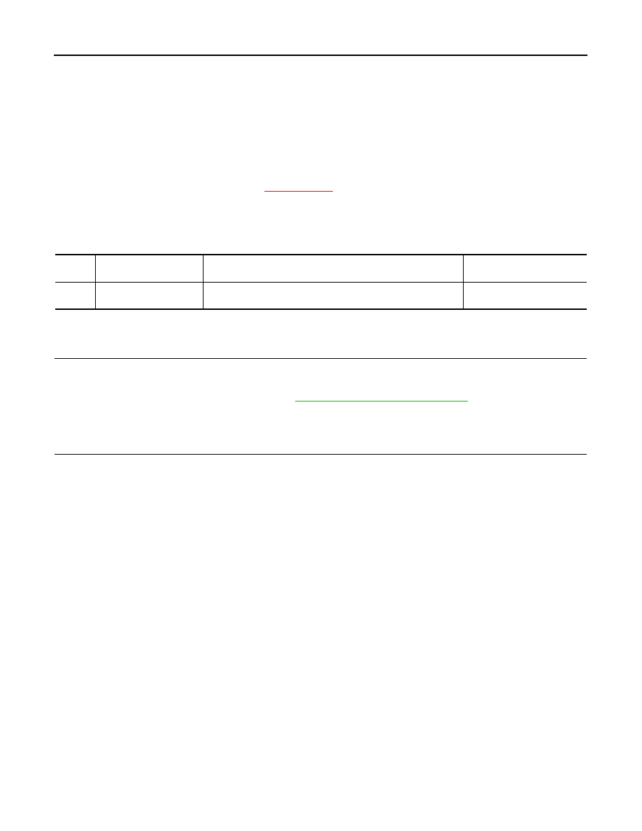
DTC
CONSULT-III display de-
scription
DTC Detection Condition
Possible cause
U1010
CONTROL UNIT (CAN)
When detecting error during the initial diagnosis of CAN control-
ler of Intelligent Key unit.
Intelligent Key unit