содержание .. 1411 1412 1413 1414 ..
Nissan Tiida C11. Manual - part 1413
INPUT SHAFT AND GEAR
TM-703
< DISASSEMBLY AND ASSEMBLY >
[6MT: RS6F94R]
C
E
F
G
H
I
J
K
L
M
A
B
TM
N
O
P
Check items below. If necessary, replace them with new ones.
• Damage, peeling, dent, uneven wear, bending, and other non-
standard conditions of the shaft.
• Excessive wear, damage, peeling, and other non-standard condi-
tions of the gears.
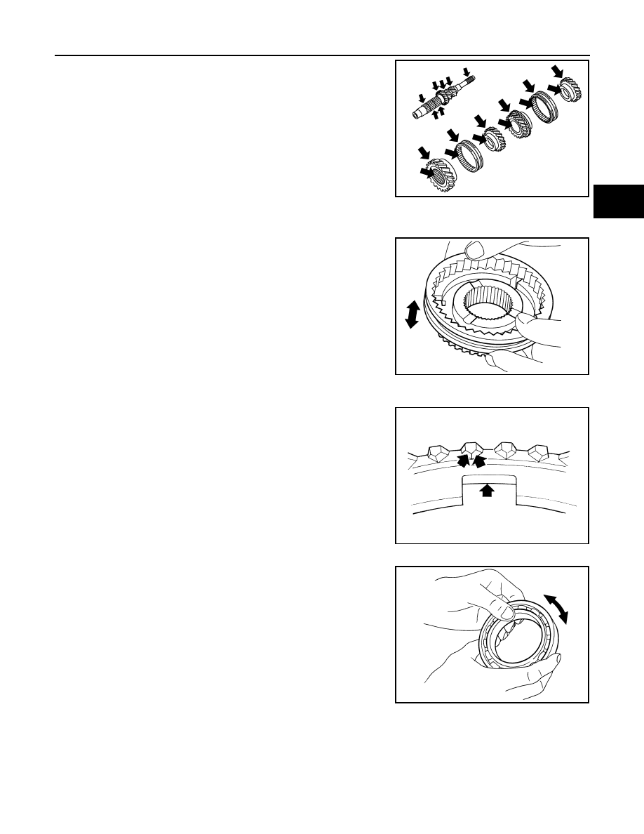
SYNCHRONIZER
Synchronizer Hub and Coupling Sleeve
Check items below. If necessary, replace them with new ones.
• Damage and excessive wear of contact surfaces of coupling
sleeve, synchronizer hub and insert key.
• Coupling sleeve and synchronizer hub must move smoothly.
Baulk Ring
Check items below. If necessary, replace them with new ones.
• If any crack, damage, or excessive wear is found on cam face of
baulk ring or working face of insert, replace it.
BEARING
Check items below. If necessary, replace them with new ones.
• Damage and rough rotation of bearing
SCIA7736E
SCIA1753J
SCIA0608J
MTF0041D