содержание .. 1334 1335 1336 1337 ..
Nissan Tiida C11. Manual - part 1336
A/T 1ST GEAR FUNCTION
TM-395
< COMPONENT DIAGNOSIS >
[TYPE 2 (4AT: RE4F03B)]
C
E
F
G
H
I
J
K
L
M
A
B
TM
N
O
P
THROTTLE POSI: Less than 1.0/8 (at all times during step 4)
SLCT LVR POSI: “D” position
-
Make sure that “GEAR” shows “2” after releasing pedal.
6.
Depress accelerator pedal to WOT (more than 7.0/8 of “THROTTLE POSI”) quickly from a speed of 20 to
25 km/h (12 to 16 MPH) until “TESTING” changes to “STOP VEHICLE” or “COMPLETED”. (It will take
approximately 3 seconds.)
If the check result NG appears on CONSULT-III screen, go to
If “STOP VEHICLE” appears on CONSULT-III screen, go to the following step.
-
Make sure that “GEAR” shows “1” when depressing accelerator pedal to WOT.
-
If “TESTING” does not appear on CONSULT-III for a long time, select “SELF-DIAGNOSTIC
RESULTS” for “TRANSMISSION”. In case a DTC other than “A/T 1ST GR FNCTN” is shown, refer
to
XX-XX, "*****"
.
7.
Stop vehicle.
8.
Follow the instruction displayed. (Check for normal shifting referring to the table below.)
9.
Make sure that “OK” is displayed. (If “NG” is displayed, refer to “Diagnostic Procedure”.)
Refer to
Refer to
XX-XX, "*****"
.
Diagnosis Procedure
INFOID:0000000001713080
1.
CHECK VALVE RESISTANCE
1.
Remove control valve assembly. Refer to
XX-XX, "*****"
.
-
Shift solenoid valve A
-
Shift solenoid valve B
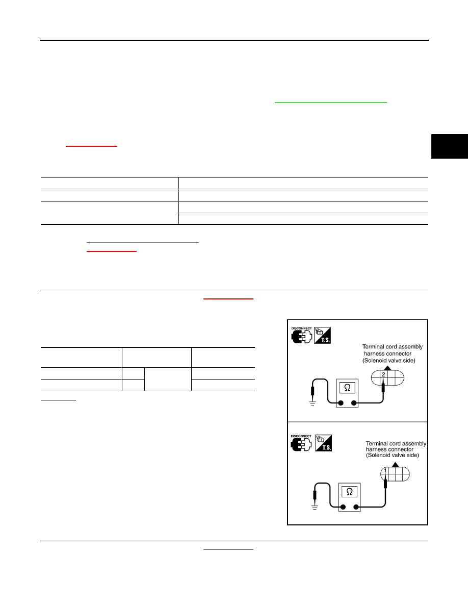
2.
Check resistance between terminal cord assembly harness con-
nector terminals and ground.
OK or NG
OK
>> GO TO 2.
NG
>> Repair or replace damaged parts.
2.
CHECK VALVE OPERATION
1.
Remove control valve assembly. Refer to
XX-XX, "*****"
.
-
Shift solenoid valve A
-
Shift solenoid valve B
Vehicle condition
Gear on actual transmission shift pattern when screen is changed to 1
→
2
→
3
→
4
No malfunction exists.
1
→
2
→
3
→
4
Malfunction for “A/T 1ST GR FNCTN ” exists.
2
→
2
→
3
→
3
4
→
3
→
3
→
4
Solenoid valve
Terminal
Resistance
(Approx.)
Shift solenoid valve A
2
Ground
20 - 30
Ω
Shift solenoid valve B
1
5 - 20
Ω
SCIA3594E