Nissan Tiida C11. Manual - part 1322


  Главная      Nissan     Nissan Tiida C11 - Service Manual


поиск по сайту            


содержание   ..  1320  1321  1322  1323   ..


Nissan Tiida C11. Manual - part 1322


A/T CONTROL SYSTEM

TM-339

< FUNCTION DIAGNOSIS >

[TYPE 2 (4AT: RE4F03B)]

C

E

F

G

H

I

J

K

L

M

A

B

TM

N

O

P

*1: Spare for vehicle speed sensor·A/T (revolution sensor)

*2: Spare for accelerator pedal position signal

*3: If these input and output signals are different, the TCM triggers the fail-safe function.

*4: Used as a condition for starting self-diagnostics; if self-diagnosis are not started, it is judged that there is some kind of error.

*5: Input by CAN communications.

*6: Output by CAN communications.

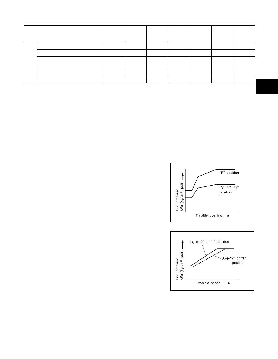
Line Pressure Control

INFOID:0000000001714314

• TCM has various line pressure control characteristics to match the driving conditions.
• An ON-OFF duty signal is sent to the line pressure solenoid valve based on TCM characteristics.
• Hydraulic pressure on the clutch and brake is electronically controlled through the line pressure solenoid

valve to accommodate engine torque. This results in smooth shift operation.

NORMAL CONTROL

The characteristic of the line pressure to the throttle opening is set
for suitable clutch operation.

BACK-UP CONTROL (ENGINE BRAKE)

If the selector lever is shifted to “2” position while driving in D

4

 or D

3,

great driving force is applied to the clutch inside the transaxle. Clutch
operating pressure (line pressure) must be increased to deal with
this driving force.

DURING SHIFT CHANGE

Out-
put

Shift solenoid valve A/B

X

(*3) X

X

Line pressure solenoid

X

(*3) X

X

Torque converter clutch solenoid 
valve

X

(*3)  X

X

Overrun clutch solenoid valve

X

X

(*3) X

X

OD OFF indicator lamp

(*6)

X

X

Control item

Line

pressure

control

Vehicle 

speed 

control

Shift     

control

Lock-up 

control

Engine 

brake 

control

Fail-safe 

function

Self-diag-

nostics 

function

SAT003J

SAT004J

TM-340

< FUNCTION DIAGNOSIS >

[TYPE 2 (4AT: RE4F03B)]

A/T CONTROL SYSTEM

The line pressure is temporarily reduced corresponding to a change
in engine torque when shifting gears (that is, when the shift solenoid
valve is switched for clutch operation) to reduce shifting shock.

AT LOW FLUID TEMPERATURE

• A/T fluid viscosity and frictional characteristics of the clutch facing change with A/T fluid temperature. Clutch

engaging or band-contacting pressure is compensated for, according to A/T fluid temperature, to stabilize
shifting quality.

• The line pressure is reduced below 60

°

C (140

°

F) to prevent shift-

ing shock due to high viscosity of A/T fluid when temperature is
low.

• Line pressure is increased to a maximum irrespective of the throt-

tle opening when A/T fluid temperature drops to 

10

°

C (14

°

F). This

pressure rise is adopted to prevent a delay in clutch and brake
operation due to extreme drop of A/T fluid viscosity at low temper-
ature.

Shift Control

INFOID:0000000001714315

The shift is regulated entirely by electronic control to accommodate vehicle speed and varying engine opera-
tions. This is accomplished by electrical signals transmitted by the revolution sensor and the ECM (accelerator
pedal position sensor). This results in improved acceleration performance and fuel economy.

CONTROL OF SHIFT SOLENOID VALVES A AND B

The TCM activates shift solenoid valves A and B according to sig-
nals from the accelerator pedal position sensor and revolution sen-
sor to select the optimum gear position on the basis of the shift
schedule memorized in the TCM.
The shift solenoid valve performs simple ON-OFF operation. When
set to “ON”, the drain circuit closes and pilot pressure is applied to
the shift valve.

RELATION BETWEEN SHIFT SOLENOID VALVES A AND B AND GEAR POSITIONS

SCIA4828E

SCIA4829E

SCIA4830E

SAT008J

A/T CONTROL SYSTEM

TM-341

< FUNCTION DIAGNOSIS >

[TYPE 2 (4AT: RE4F03B)]

C

E

F

G

H

I

J

K

L

M

A

B

TM

N

O

P

CONTROL OF SHIFT VALVES A AND B

Pilot pressure generated by the operation of shift solenoid valves A and B is applied to the end face of shift
valves A and B.
The figure above shows the operation of shift valve B. When the shift solenoid valve is “ON”, pilot pressure
applied to the end face of the shift valve overcomes spring force, moving the valve upward.

Lock-up Control

INFOID:0000000001714316

The torque converter clutch piston in the torque converter is locked to eliminate torque converter slip and to
increase power transmission efficiency. The solenoid valve is controlled by an ON-OFF duty signal sent from
the TCM. The signal is converted to an oil pressure signal which controls the torque converter clutch piston.

CONDITIONS FOR LOCK-UP OPERATION

When vehicle is driven in 3rd and 4th gear positions, vehicle speed and throttle opening are detected. If the
detected values fall within the lock-up zone memorized in the TCM, lock-up is performed.

TORQUE CONVERTER CLUTCH SOLENOID VALVE CONTROL

Gear position

1

2

3

4

Shift solenoid valve A

ON (Closed)

OFF (Open)

OFF (Open)

ON (Closed)

Shift solenoid valve B

ON (Closed)

ON (Closed)

OFF (Open)

OFF (Open)

SAT009J

OD

ON

OFF

Selector lever

“D” position

Gear position

D

4

D

3

Vehicle speed sensor

More than set value

Throttle position sensor

Less than set opening

Closed throttle position switch

OFF

A/T fluid temperature sensor

More than 40

°

C (104

°

F)

TM-342

< FUNCTION DIAGNOSIS >

[TYPE 2 (4AT: RE4F03B)]

A/T CONTROL SYSTEM

Lock-up Control System Diagram

Lock-up Released 

In the lock-up released state, the torque converter clutch control valve is set into the unlocked state by drain-
ing the torque converter clutch piston applying pressure and the torque converter clutch piston release pres-
sure is generated.
In this way, the torque converter clutch piston is not coupled.

Lock-up Applied

In the lock-up applied state, the torque converter clutch control valve is set into the locked state by generating
the torque converter clutch piston applying pressure and the torque converter clutch piston release pressure is
drained.
In this way, the torque converter clutch piston is pressed and coupled.

SMOOTH LOCK-UP CONTROL 

When shifting from the lock-up released state to the lock-up applied state, the current output to the torque con-
verter clutch solenoid is controlled with the TCM. In this way, when shifting to the lock-up applied state, the
torque converter clutch is temporarily set to the half-clutched state to reduce the shock.

Half-clutched State

The current output from the TCM to the torque converter clutch solenoid is varied to steadily increase the
torque converter clutch solenoid pressure.
In this way, the lock-up applying pressure gradually rises and while the torque converter clutch piston is put
into half-clutched status, the torque converter clutch piston applying pressure is increased and the coupling is
completed smoothly.

Engine Brake Control (Overrun Clutch Control)

INFOID:0000000001714317

Forward one-way clutch is used to reduce shifting shocks in downshifting operations. This clutch transmits
engine torque to the wheels. However, drive force from the wheels is not transmitted to the engine because
the one-way clutch rotates idle. This means the engine brake is not effective.
The overrun clutch operates when the engine brake is needed.

SCIA5623E


содержание   ..  1320  1321  1322  1323   ..