Nissan Tiida C11. Manual - part 1299


  Главная      Nissan     Nissan Tiida C11 - Service Manual


поиск по сайту            


содержание   ..  1297  1298  1299  1300   ..


Nissan Tiida C11. Manual - part 1299


REPAIR FOR COMPONENT PARTS

TM-247

< DISASSEMBLY AND ASSEMBLY >

[TYPE 1 (4AT: RE4F03B)]

C

E

F

G

H

I

J

K

L

M

A

B

TM

N

O

P

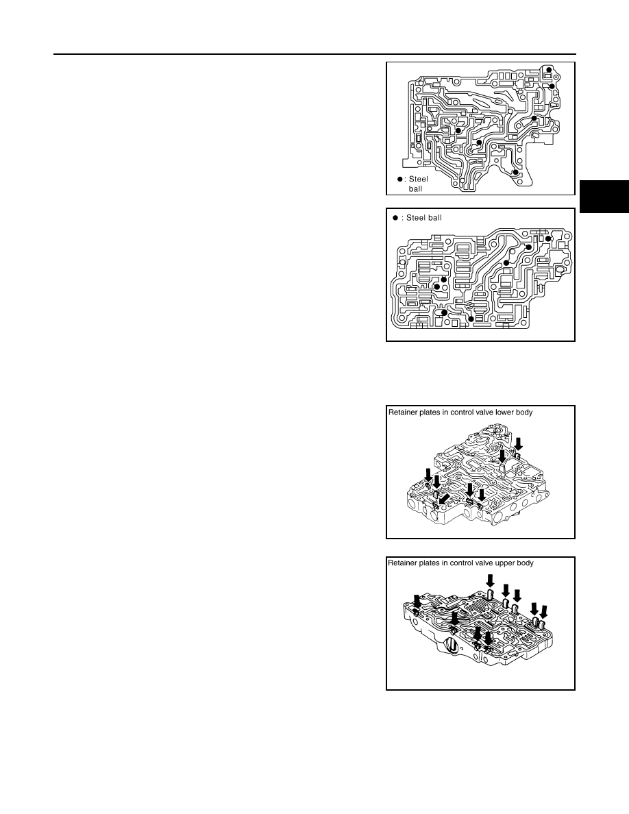
12. Check to see that steel balls are properly positioned in control

valve inter body and then remove them.

CAUTION:

Do not lose steel balls.

13. Check to see that steel balls are properly positioned in control

valve upper body and then remove them.

CAUTION:

Do not lose steel balls.

INSPECTION

Control Valve Lower and Upper Bodies

CAUTION:

Do not lose these parts.
• Check to see that retainer plates are properly positioned in control

valve lower body.

• Check to see that retainer plates are properly positioned in control

valve upper body.

Oil Strainer

SAT870J

SAT871J

SCIA4978E

SCIA4979E

TM-248

< DISASSEMBLY AND ASSEMBLY >

[TYPE 1 (4AT: RE4F03B)]

REPAIR FOR COMPONENT PARTS

Check wire netting of oil strainer for damage. Replace if necessary.

Shift Solenoid Valves “A” and “B”, Line Pressure Solenoid Valve, Torque Converter Clutch Solenoid Valve and Over-
run Clutch Solenoid Valve

Measure resistance.
• For shift solenoid valve A, refer to 

TM-87, "Component Inspection"

.

• For shift solenoid valve B, refer to 

TM-91, "Component Inspection"

.

• For line pressure solenoid valve, refer to 

TM-84, "Component

Inspection"

.

• For torque converter clutch solenoid valve, refer to 

TM-75, "Com-

ponent Inspection"

• For overrun clutch solenoid valve, refer to 

TM-75, "Component

Inspection"

.

A/T Fluid Temperature Sensor

Measure resistance.
• For A/T fluid temperature sensor, refer to 

TM-50, "Component Inspection"

.

Line Pressure Relief Valve Springs and Torque Converter Pressure Holding Spring

• Check each spring for damage or deformation. Also measure free

length and outer diameter. Refer to 

TM-321, "Control Valves"

.

• Replace springs if deformed or fatigued.

ASSEMBLY

1.

Install control valve upper, inter and lower body.

a.

Place oil circuit of control valve upper body face up. Install steel
balls in their proper positions.

SCIA3291E

SCIA3485E

SAT138D

SAT871J

REPAIR FOR COMPONENT PARTS

TM-249

< DISASSEMBLY AND ASSEMBLY >

[TYPE 1 (4AT: RE4F03B)]

C

E

F

G

H

I

J

K

L

M

A

B

TM

N

O

P

b.

Install reamer bolts (F) from bottom of control valve upper body
(1). Using reamer bolts (F) as guides, install separating plate (2)
as a set.

c.

Install pilot filter (1) on control valve upper body (2).

d.

Place control valve inter body as shown (side of control valve
lower body face up). Install steel balls in their proper positions.

e.

Install control valve inter body (1) on control valve upper body
(2) using reamer bolts (F) as guides.

CAUTION:

Do not dislocate or drop steel balls.

f.

Install check balls (1), line pressure relief valve springs (2) and
torque converter pressure holding spring (3) in their proper posi-
tions in control valve lower body (4).

SCIA7010E

SCIA7011E

SAT870J

SCIA7012E

SCIA6491J

TM-250

< DISASSEMBLY AND ASSEMBLY >

[TYPE 1 (4AT: RE4F03B)]

REPAIR FOR COMPONENT PARTS

g.

Install bolts (E) from bottom of control valve lower body (1).
Using bolts (E) as guides, install separating plate (2) as a set.

h.

Install support plates (3) on control valve lower body (1).

i.

Install control valve lower body (1) on control valve inter body (2)
using reamer bolts (F) as guides, and tighten reamer bolts (F)
slightly.

2.

Install O-rings on solenoid valves and terminal body.

3.

Install and tighten bolts.
(1): Control valve upper body
(2): Control valve inter body
(3): Control valve lower body
(4): Support plate

SCIA7013E

SCIA7014E

SCIA7180E

SCIA7058E


содержание   ..  1297  1298  1299  1300   ..