содержание .. 1247 1248 1249 1250 ..
Nissan Tiida C11. Manual - part 1249
DTC P0705 PARK/NEUTRAL POSITION (PNP) SWITCH
TM-47
< COMPONENT DIAGNOSIS >
[TYPE 1 (4AT: RE4F03B)]
C
E
F
G
H
I
J
K
L
M
A
B
TM
N
O
P
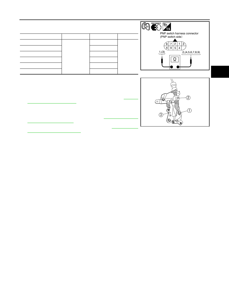
1.
Check continuity between PNP switch harness connector termi-
nals.
2.
If NG, check again with control cable (2) disconnected from
manual shaft of A/T assembly. Refer to step 1.
(1): Lock nut
(3): Manual shaft
3.
If OK on step 2, adjust control cable (2). Refer to
.
4.
If NG on step 2, remove PNP switch from A/T and check conti-
nuity of PNP switch terminals. Refer to step 1.
5.
If OK on step 4, adjust PNP switch. Refer to
.
6.
If NG on step 4, replace PNP switch. Refer to
Neutral Position (PNP) Switch"
.
Selector lever position
Connector
Terminal
Continuity
“P”
F25
1 - 2, 3 - 7
Yes
*Continuity
should not
exist in posi-
tions other
than the
specified
positions.
“R”
3 - 8
“N”
1 - 2, 3 - 9
“D”
3 - 6
“2”
3 - 5
“1”
3 - 4
SCIA5588E
SCIA6370J