Nissan Tiida C11. Manual - part 1246


  Главная      Nissan     Nissan Tiida C11 - Service Manual


поиск по сайту            


содержание   ..  1244  1245  1246  1247   ..


Nissan Tiida C11. Manual - part 1246


DIAGNOSIS SYSTEM (TCM)

TM-35

< FUNCTION DIAGNOSIS >

[TYPE 1 (4AT: RE4F03B)]

C

E

F

G

H

I

J

K

L

M

A

B

TM

N

O

P

DIAGNOSIS SYSTEM (TCM)

CONSULT-III Function (TRANSMISSION)

INFOID:0000000001694438

CONSULT-III can display each diagnostic item using the diagnostic test models shown following.

SELF-DIAGNOSTIC RESULT MODE

Operation Procedure

After performing SELF-DIAGNOSTIC RESULT MODE, place check marks for results on the 

TM-11, "Diagnos-

tic Work Sheet"

. Reference pages are provided following the items.

Display Items List

TCM diagnostic mode

Description

WORK SUPPORT

Supports inspections and adjustments. Commands are transmitted to the TCM for setting the status 
suitable for required operation, input/output signals are received from the TCM and received data is 
displayed.

SELF-DIAG RESULTS

Displays TCM self-diagnosis results.

DATA MONITOR

Displays TCM input/output data in real time.

CAN DIAG SUPPORT MNTR

The result of transmit/receive diagnosis of CAN communication can be read.

ACTIVE TEST

Operation of electrical loads can be checked by sending drive signal to them.

FUNCTION TEST

Conducted by CONSULT-III instead of a technician to determine whether each system is “OK” or “NG”.

ECU PART NUMBER

TCM part number can be read.
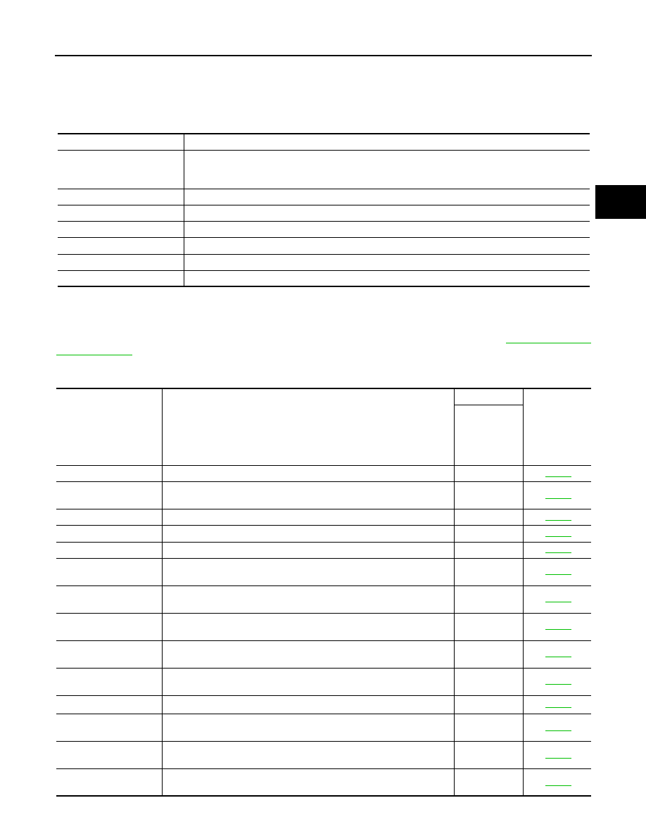
Items (CONSULT-III 

screen terms)

Malfunction is detected when...

OBD (DTC)

 Reference 

page

MIL indicator 
lamp*1, “EN-

GINE” with 

CONSULT-III 

or GST

CAN COMM CIRCUIT

• When malfunction is detected in CAN communication line.

U1000

TM-43

PNP SW/CIRC

• TCM does not receive the correct voltage signal (based on the gear 

position) from the switch.

P0705

TM-44

ATF TEMP SEN/CIRC

• TCM receives an excessively low or high voltage from the sensor.

P0710

TM-48

VHCL SPEED SEN-A/T

• TCM does not receive the proper voltage signal from the sensor.

P0720

TM-52

ENGINE SPEED SIG

• TCM does not receive the proper voltage signal from the ECM.

P0725

TM-56

A/T 1ST GR FNCTN

• A/T cannot be shifted to the 1st gear position even if electrical circuit 

is good.

P0731

*2

TM-59

A/T 2ND GR FNCTN

• A/T cannot be shifted to the 2nd gear position even if electrical circuit 

is good.

P0732

*2

TM-62

A/T 3RD GR FNCTN

• A/T cannot be shifted to the 3rd gear position even if electrical circuit 

is good.

P0733

*2

TM-65

A/T 4TH GR FNCTN

• A/T cannot be shifted to the 4th gear position even if electrical circuit 

is good.

P0734

*2

TM-68

T/C CLUTCH SOL/V

• TCM detects an improper voltage drop when it tries to operate the so-

lenoid valve.

P0740

TM-73

A/T TCC S/V FNCTN

• A/T cannot perform lock-up even if electrical circuit is good.

P0744

*2

TM-76

LINE PRESSURE S/V

• TCM detects an improper voltage drop when it tries to operate the so-

lenoid valve.

P0745

TM-81

SHIFT SOLENOID/V A

• TCM detects an improper voltage drop when it tries to operate the so-

lenoid valve.

P0750

TM-85

SHIFT SOLENOID/V B

• TCM detects an improper voltage drop when it tries to operate the so-

lenoid valve.

P0755 

TM-89

TM-36

< FUNCTION DIAGNOSIS >

[TYPE 1 (4AT: RE4F03B)]

DIAGNOSIS SYSTEM (TCM)

*1: Refer to 

TM-33, "Malfunction Indicator Lamp (MIL)"

.

*2: These malfunctions cannot be displayed MIL if another malfunction is assigned to MIL.

DATA MONITOR MODE

Display Items List

 X: Standard, —: Not applicable, 

: Option

OVERRUN CLUTCH S/
V

• TCM detects an improper voltage drop when it tries to operate the so-

lenoid valve.

P1760

TM-93

VHCL SPEED SEN-
MTR

• TCM does not receive the proper voltage signal from the sensor.

TM-97

BATT/FLUID TEMP 
SEN

• TCM receives an excessively low or high voltage from the sensor.

TM-99

TURBINE SENSOR

• TCM does not receive proper voltage signal from sensor.

TM-104

CONTROL UNIT (RAM)

• TCM memory (RAM) is malfunctioning.

TM-108

CONTROL UNIT (ROM)

• TCM memory (ROM) is malfunctioning.

TM-108

INITIAL START

• This is not a malfunction message (Whenever shutting off a power 

supply to the TCM, this message appears on the screen). Refer to 

TM-

109

.

TM-109

No failure
(NO SELF DIAGNOS-
TIC FAILURE INDICAT-
ED FURTHER 
TESTING MAY BE RE-
QUIRED)

• No failure has been detected.

Items (CONSULT-III 

screen terms)

Malfunction is detected when...

OBD (DTC)

 Reference 

page

MIL indicator 
lamp*1, “EN-

GINE” with 

CONSULT-III 

or GST

Monitored item (Unit)

Monitor Item Selection

Remarks

TCM INPUT 

SIGNALS

MAIN SIG-

NALS

SELEC-

TION FROM 

MENU

VHCL/S SE-A/T (km/h)

X

Revolution sensor

VHCL/S SE-MTR (km/h)

X

Vehicle speed display may not be accu-
rate under approx. 10 km/h (6 mph). It 
may not indicate 0 km/h (0 mph) when 
vehicle is stationary.

THRTL POS SEN (V)

X

FLUID TEMP SE (V) 

X

BATTERY VOLT (V)

X

ENGINE SPEED (rpm) 

X

X

TURBINE REV (rpm) 

X

OVERDRIVE SW (ON/OFF)

X

PN POSI SW (ON/OFF)

X

R POSITION SW (ON/OFF)

X

D POSITION SW (ON/OFF)

X

2 POSITION SW (ON/OFF)

X

1 POSITION SW (ON/OFF)

X

DIAGNOSIS SYSTEM (TCM)

TM-37

< FUNCTION DIAGNOSIS >

[TYPE 1 (4AT: RE4F03B)]

C

E

F

G

H

I

J

K

L

M

A

B

TM

N

O

P

DTC WORK SUPPORT MODE

Display Items List

ASCD-CRUISE (ON/OFF)

X

Signal input with CAN communication.

ASCD-OD CUT (ON/OFF)

X

KICKDOWN SW (ON/OFF)

X

Not mounted but displayed.

POWERSHIFT SW (ON/OFF)

X

CLOSED THL/SW (ON/OFF)

X

Signal input with CAN communication.

W/O THRL/P-SW (ON/OFF)

X

*SHIFT S/V A (ON/OFF)

Displays status of check signal (reinput 
signal) for TCM control signal output. Re-
mains unchanged when solenoid valves 
are open or shorted.

*SHIFT S/V B (ON/OFF)

*OVRRUN/C S/V (ON/OFF)

HOLD SW (ON/OFF)

X

Not mounted but displayed.

BRAKE SW (ON/OFF)

X

Stop lamp switch

GEAR

X

Gear position recognized by the TCM up-
dated after gear-shifting

SLCT LVR POSI

X

Selector lever position is recognized by 
the TCM.
For fail-safe operation, the specific value 
used for control is displayed.

VEHICLE SPEED (km/h)

X

Vehicle speed recognized by the TCM.

THROTTLE POSI (0.0/8)

X

Degree of opening for accelerator recog-
nized by the TCM
For fail-safe operation, the specific value 
used for control is displayed.

LINE PRES DTY (%)

X

TCC S/V DUTY (%)

X

SHIFT S/V A (ON/OFF)

X

SHIFT S/V B (ON/OFF)

X

OVERRUN/C S/V (ON/OFF)

X

SELF-D DP LMP (ON/OFF)

X

TC SLIP RATIO (0.000)

TC SLIP SPEED (rpm)

Difference between engine speed and 
torque converter input shaft speed

Voltage (V) 

Displays the value measured by the volt-
age probe.

Frequency (Hz)

The value measured by the pulse probe 
is displayed.

DUTY-HI (high) (%)

DUTY-LOW (low) (%)

PLS WIDTH-HI (ms) 

PLS WIDTH-LOW (ms) 

Monitored item (Unit)

Monitor Item Selection

Remarks

TCM INPUT 

SIGNALS

MAIN SIG-

NALS

SELEC-

TION FROM 

MENU

TM-38

< FUNCTION DIAGNOSIS >

[TYPE 1 (4AT: RE4F03B)]

DIAGNOSIS SYSTEM (TCM)

Diagnosis Procedure without CONSULT-III

INFOID:0000000001694439

 TCM SELF-DIAGNOSTIC PROCEDURE

Description

If a malfunction occurs in electrical system, turning ignition switch ON will illuminate OD OFF indicator lamp for
2 seconds. To detect a malfunction, entering a self-diagnosis start signal retrieves information on malfunctions
from memory and indicates malfunction by blinking OD OFF indicator lamp.

Diagnostic Procedure

1.

CHECK OD OFF INDICATOR LAMP

1.

Park vehicle on flat surface.

2.

Move selector lever to “P” position.

3.

Turn ignition switch OFF. Wait at least 5 seconds.

DTC work support item

Description

Check item

1ST GR FNCTN P0731

Following items for “A/T 1st gear function (P0731)” can be con-
firmed.
• Self-diagnosis status (whether the diagnosis is being performed 

or not)

• Self-diagnostic results (OK or NG)

• Shift solenoid valve A
• Shift solenoid valve B
• Each clutch
• Hydraulic  control circuit

2ND GR FNCTN P0732

Following items for “A/T 2nd gear function (P0732)” can be con-
firmed.
• Self-diagnosis status (whether the diagnosis is being performed 

or not)

• Self-diagnostic results (OK or NG)

• Shift solenoid valve B
• Each clutch
• Hydraulic  control circuit

3RD GR FNCTN P0733

Following items for “A/T 3rd gear function (P0733)” can be con-
firmed.
• Self-diagnosis status (whether the diagnosis is being performed 

or not)

• Self-diagnostic results (OK or NG)

• Shift solenoid valve A
• Each clutch
• Hydraulic  control circuit

4TH GR FNCTN P0734

Following items for “A/T 4th gear function (P0734)” can be con-
firmed.
• Self-diagnosis status (whether the diagnosis is being performed 

or not)

• Self-diagnostic results (OK or NG)

• Shift solenoid valve A
• Shift solenoid valve B
• Overrun clutch solenoid valve
• Line pressure solenoid valve
• Each clutch
• Hydraulic  control circuit

TCC S/V FNCTN P0744

Following items for “A/T TCC S/V function (lock-up) (P0744)” can 
be confirmed.
• Self-diagnosis status (whether the diagnosis is being performed 

or not)

• Self-diagnostic results (OK or NG)

• Torque converter clutch sole-

noid valve

• Each clutch
• Hydraulic  control circuit

SCIA5472E


содержание   ..  1244  1245  1246  1247   ..