Nissan Tiida C11. Manual - part 116


  Главная      Nissan     Nissan Tiida C11 - Service Manual


поиск по сайту            


содержание   ..  114  115  116  117   ..


Nissan Tiida C11. Manual - part 116


CHG-42

< SYMPTOM DIAGNOSIS >

[K9K]

CHARGING SYSTEM

SYMPTOM DIAGNOSIS

CHARGING SYSTEM

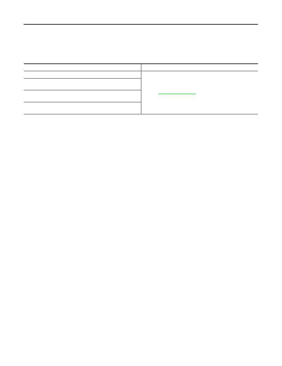
Symptom Table

INFOID:0000000001724516

Symptom

Reference

Battery discharged

Refer to 

CHG-33, "Work Flow"

.

The charge warning lamp does not illuminate when the ignition 
switch is set to ON.

The charge warning lamp does not turn OFF after the engine 
starts.

The charging warning lamp turns ON when increasing the engine 
speed.

CHG

GENERATOR

CHG-43

< ON-VEHICLE REPAIR >

[K9K]

C

D

E

F

G

H

I

J

K

L

B

A

O

P

N

ON-VEHICLE REPAIR

GENERATOR

Removal and Installation

INFOID:0000000001689502

REMOVAL

1.

Disconnect the battery cable from the negative terminal.

2.

Remove RH fender protector partially. 

3.

Remove fuel injection pipe protector. 

4.

Remove drive belt. Refer to 

EM-263, "Removal and Installation"

.

5.

Disconnect generator connector.

6.

Remove “B” terminal nut and “B” terminal harness.

7.

Remove upper generator bolt.

8.

Release lower generator bolt, then push it aside.

9.

Remove generator with lower bolt.
NOTE:
Pull generator to the front side from upside. Turn, then pull lower side of generator with lower bolt.

INSTALLATION

Installation is in the reverse order of removal.

CAUTION:

Be sure to tighten “B” terminal nut carefully.
• Install generator, and check tension of belt. Refer to 

EM-263, "Inspection and Adjustment"

.

1.

Generator connector

2.

Generator bolt

3.

Generator

4.

“B” terminal harness

5.

“B” terminal nut

JPMIA0263GB

CHG-44

< SERVICE DATA AND SPECIFICATIONS (SDS) 

[K9K]

SERVICE DATA AND SPECIFICATIONS (SDS)

SERVICE DATA AND SPECIFICATIONS (SDS)

SERVICE DATA AND SPECIFICATIONS (SDS)

Generator

INFOID:0000000001691231

Applied model

K9K

Type

0 124 525 082

BOSCH make

Nominal rating

[V - A]

Ground polarity

Minimum revolution under no-load (When 13.5 V 
is applied)

[rpm]

Hot output current (When 13.5 V is applied)

[A/rpm]

Regulated output voltage

[V]

Minimum length of brush

[mm (in)]

Brush spring pressure

[N (g, oz)]

Slip ring minimum outer diameter

[mm (in)]

Rotor (Field coil) resistance

[

]

CL-1

TRANSMISSION & DRIVELINE

C

E

F

G

H

I

J

K

L

M

SECTION 

CL

A

B

CL

N

O

P

CONTENTS

CLUTCH

SERVICE INFORMATION  ............................

2

PRECAUTIONS ...................................................

2

Precaution for Supplemental Restraint System 
(SRS) "AIR BAG" and "SEAT BELT PRE-TEN-
SIONER" .................................................................
..

2

Service Notice or Precaution .....................................

2

PREPARATION ...................................................

3

Special Service Tool  .................................................

3

Commercial Service Tool  ..........................................

3

NOISE, VIBRATION AND HARSHNESS 
(NVH) TROUBLESHOOTING  .............................

4

NVH Troubleshooting Chart  ......................................

4

CLUTCH PEDAL  .................................................

5

On-vehicle Inspection and Adjustment ......................

5

Removal and Installation ...........................................

6

CLUTCH FLUID ...................................................

8

Air Bleeding Procedure .............................................

8

CLUTCH MASTER CYLINDER  .........................

9

Removal and Installation  ..........................................

9

CSC (CONCENTRIC SLAVE CYLINDER)  .......

11

Removal and Installation  .........................................

11

CLUTCH PIPING ...............................................

12

Removal and Installation  .........................................

12

CLUTCH DISC, CLUTCH COVER AND FLY-
WHEEL ..............................................................

13

Removal and Installation  .........................................

13

SERVICE DATA AND SPECIFICATIONS 
(SDS) .................................................................

16

Clutch Control System .............................................

16

Clutch Pedal  ............................................................

16

Clutch Disc  ..............................................................

16

Clutch Cover ............................................................

16


содержание   ..  114  115  116  117   ..