содержание .. 1107 1108 1109 1110 ..
Nissan Tiida C11. Manual - part 1109
PCS
IPDM E/R (INTELLIGENT POWER DISTRIBUTION MODULE ENGINE ROOM)
PCS-19
< ECU DIAGNOSIS >
[IPDM E/R]
C
D
E
F
G
H
I
J
K
L
B
A
O
P
N
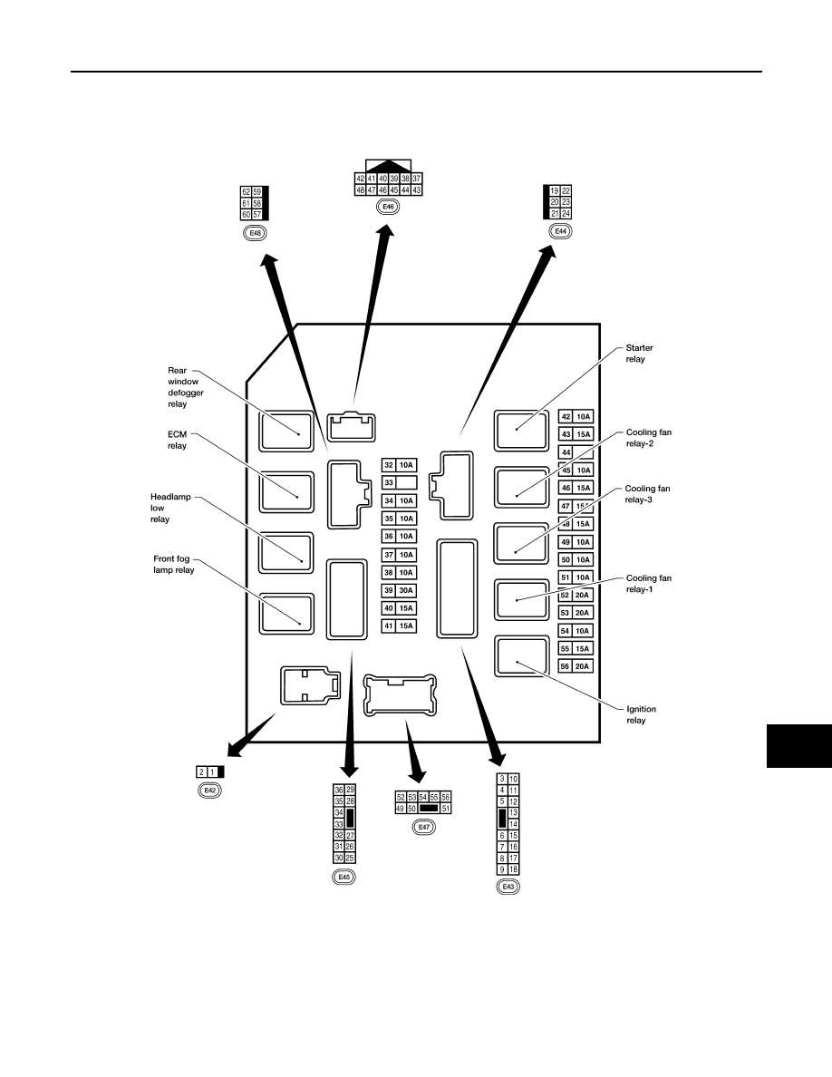
Terminal Layout
INFOID:0000000001697596
TERMINAL LAYOUT
Physical Values
INFOID:0000000001697597
PHYSICAL VALUES
WKIA5666E