содержание .. 1075 1076 1077 1078 ..
Nissan Tiida C11. Manual - part 1077
DOOR MIRROR
MIR-7
< REMOVAL AND INSTALLATION >
C
D
E
F
G
H
I
J
K
M
A
B
MIR
N
O
P
REMOVAL AND INSTALLATION
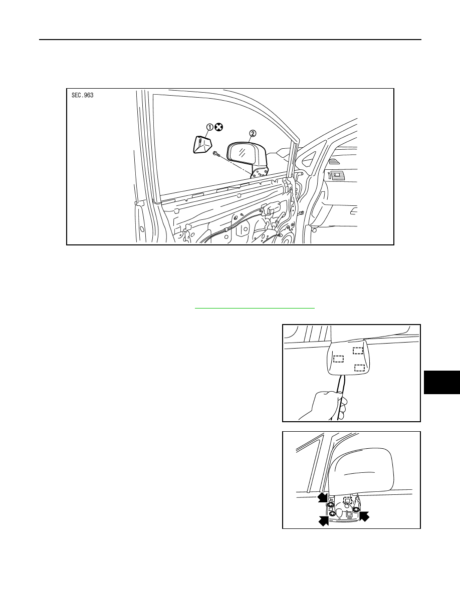
DOOR MIRROR
Removal and Installation
INFOID:0000000001716808
CAUTION:
Be careful not to damage the mirror body.
REMOVAL
1.
Remove the front door finisher. Refer to
INT-13, "Removal and Installation"
2.
Disconnect the harness connector of door mirror.
3.
Using a suitable tool remove door mirror base cover.
CAUTION:
• Do not reuse the disassembled door mirror base cover.
• Be careful not to damage the door panel with a tool.
4.
Remove the door mirror bolts, and remove the door mirror
assembly.
CAUTION:
Do not use force to remove the door mirror assembly by
force because it is attached by clip.
INSTALLATION
Installation is in the reverse order of removal.
PIIB2638J
1.
Door mirror base cover
2.
Door mirror
PIIB2679E
PIIB6288E