содержание .. 1008 1009 1010 1011 ..
Nissan Tiida C11. Manual - part 1010
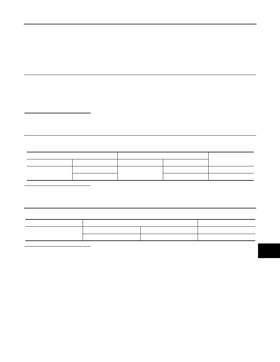
LAN
MAIN LINE BETWEEN DLC AND AV CIRCUIT
LAN-297
< COMPONENT DIAGNOSIS >
[CAN SYSTEM (TYPE 20)]
C
D
E
F
G
H
I
J
K
L
B
A
O
P
N
COMPONENT DIAGNOSIS
MAIN LINE BETWEEN DLC AND AV CIRCUIT
Diagnosis Procedure
INFOID:0000000001333903
INSPECTION PROCEDURE
1.
CHECK CONNECTOR
1.
Turn the ignition switch OFF.
2.
Disconnect the battery cable from the negative terminal.
3.
Check the following terminals and connectors for damage, bend and loose connection (connector side
and harness side).
-
Harness connector M14
-
Harness connector B3
Is the inspection result normal?
YES
>> GO TO 2.
NO
>> Repair the terminal and connector.
2.
CHECK HARNESS CONTINUITY (OPEN CIRCUIT)
1.
Disconnect the harness connectors M14 and B3.
2.
Check the continuity between the data link connector and the harness connector.
Is the inspection result normal?
YES
>> GO TO 3.
NO
>> Repair the main line between the data link connector and the harness connector M14.
3.
CHECK HARNESS CONTINUITY (OPEN CIRCUIT)
Check the continuity between the harness connector terminals.
Is the inspection result normal?
YES (Present error)>>Check CAN system type decision again.
YES (Past error)>>Error was detected in the main line between the data link connector and the NAVI control
unit.
NO
>> Repair the main line between the harness connector B3 and the NAVI control unit.
Data link connector
Harness connector
Continuity
Connector No.
Terminal No.
Connector No.
Terminal No.
M22
6
M14
1
Existed
14
17
Existed
Connector No.
Terminal No.
Continuity
B3
1
16
Existed
17
32
Existed