содержание .. 12 13 14 15 ..
Nissan Tiida C11. Manual - part 14
AV-50
< FUNCTION DIAGNOSIS >
[AUDIO WITH NAVIGATION]
DIAGNOSIS SYSTEM (NAVI CONTROL UNIT)
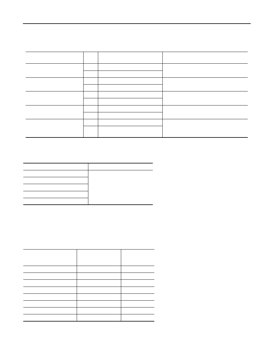
ALL SIGNALS
• Displays the status of the following vehicle signals inputted to the NAVI control unit.
• For each signal, actual signal can be compared with the condition recognized on the system.
SELECTION FROM MENU
Allows the technician to select which vehicle signals should be displayed and displays the status of the
selected vehicle signals.
AV communication monitor
AV&NAVI C/U
• Displays the communication status from NAVI control unit to each unit as well as the error counter.
• The error counter displays “OK” if no malfunction was detected in the past and displays “0” if a malfunction is
detected. It increases by 1 if the condition is normal at the next ignition switch ON cycle. The upper limit of
the counter is 39.
AUDIO
• Displays the NAVI control unit communication status and the error counter.
Display Item
Dis-
play
Vehicle status
Remarks
VHCL SPD SIG
ON
Vehicle speed >0 km/h (0 MPH)
Changes in indication may be delayed. This is
normal.
OFF
Vehicle speed =0 km/h (0 MPH)
PKB SIG
ON
Parking brake is applied.
Changes in indication may be delayed. This is
normal.
OFF
Parking brake is released.
ILLUM SIG
ON
Lighting switch ON
—
OFF
Lighting switch OFF
IGN SIG
ON
Ignition switch ON
—
OFF
Ignition switch in ACC position
REV SIG
ON
Selector lever in R position
Changes in indication may be delayed. This is
normal.
OFF
Selector lever in any position other
than R
Item to be selected
Description
VHCL SPD SIG
The same as when “ALL SIGNALS”
is selected.
PKB SIG
ILLUM SIG
IGN SIG
REV SIG
Items
Display (Current)
Malfunction
counter
(Past)
TRANSMIT DIAG
OK / UNKWN
OK / 0 – 39
PANEL SWITCH
OK/ UNKWN
OK / 0 – 39
SW SECONDARY
—
—
RR CONTROL SW
—
—
STEERING SW
OK / UNKWN
OK / 0 – 39
AUDIO
OK / UNKWN
OK / 0 – 39
SPEAKER AMP
OK / UNKWN
OK / 0 – 39
FM MULTI
OK / UNKWN
OK / 0 – 39