Mitsubishi Outlander XL. Manual - part 927


  Index      Mitsubishi     Mitsubishi Outlander XL - service repair manual 2007 year


Search            copyright infringement  


Content   ..  925  926  927  928   ..


Mitsubishi Outlander XL. Manual - part 927


DTC SET CONDITIONS
This  DTC  is  set  if  there  is  abnormal  resistance
between the input terminals of the passenger's seat
belt pre-tensioner (squib).

TROUBLESHOOTING HITS

Damaged wiring harnesses or connectors

Short to the power supply in the passenger's seat
belt pre-tensioner (squib) harness

Malfunction of the SRS-ECU

DIAGNOSIS

Required Special Tools:

MB991958: Scan Tool (M.U.T.-III Sub Assembly)

MB991824: Vehicle Communication Interface (V.C.I.)

MB991827: M.U.T.-III USB Cable

MB991910:  M.U.T.-III  Main  Harness  A  (Vehicles  with
CAN Communication System)

MB991865: Dummy resistor

MB991884: Resister harness

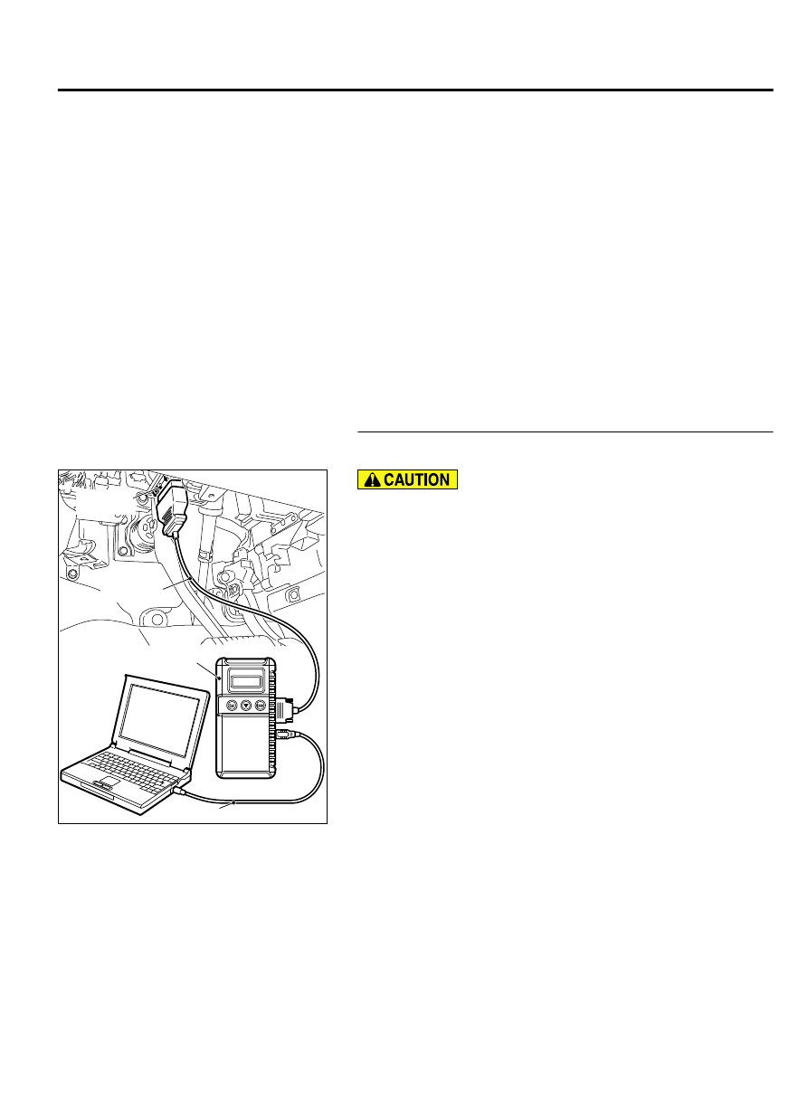
STEP 1. Using scan tool MB991958, diagnose the CAN bus
line.

ZC501967

AC404789

ZC5019680000

MB991824

MB991827

MB991910

Data link

connector

To prevent damage to scan tool MB991958, always turn the
ignition  switch  to  the  "LOCK"  (OFF)  position  before
connecting or disconnecting scan tool MB991958.

(1)

Connect scan tool MB991958. Refer to "How to connect the
scan tool P.52B-31."

(2)

Turn the ignition switch to the "ON" position.

(3)

Diagnose the CAN bus line.

(4)

Turn the ignition switch to the "LOCK" (OFF) position.

Q:Is the CAN bus line found to be normal?

YES:

 Go to Step 2.

NO:

 Repair the CAN bus line (Refer to GROUP 54D,

Diagnosis P.54D-17).

SUPPLEMENTAL RESTRAINT SYSTEM (SRS)

52B-239

SRS AIR BAG DIAGNOSIS

STEP 2. Recheck for diagnostic trouble code.

ZC501967

AC404789

ZC5019680000

MB991824

MB991827

MB991910

Data link

connector

Check again if the DTC is set.

(1)

Erase the DTC.

(2)

Turn the ignition switch to "ON" position.

(3)

Check if the DTC is set.

(4)

Turn the ignition switch to the "LOCK" (OFF) position.

Q:Is the DTC set?

YES:

 Go to Step 3.

NO:

 There is an intermittent malfunction such as poor

engaged connector(s) or open circuit (Refer to GROUP 00,
How to Cope with Intermittent Malfunction P.00-15).

STEP 3. Check the passenger's seat belt pre-tensioner.
(Using scan tool MB991958, read the diagnostic trouble
code.)

(1)

Disconnect the negative battery terminal.

ZC6018230001

Seat belt  
pre-tensioner

Floor wiring harness side
connector (2-pin, black)

Locking  
button

Flat-tipped
screwdriver

(2)

Disconnect  passenger's  seat  belt  pre-tensioner  connector
D-130.  Use  a  flat-tipped  screwdriver  to  unlock  the  locking
button at the harness side connector by withdrawing it toward
you in two stages, and then disconnect the connector.

ZC600214

Harness side  
connector

MB991865 
(Dummy resistor: 3  


)

MB991884  
(Resistor harness)

0000

(3)

Connect special tool MB991865 to special tool MB991884.

(4)

Connect special tool MB991884 to the D-130 harness side
connector.

(5)

Connect the negative battery terminal.

(6)

Erase diagnostic trouble code memory, and then check the
diagnostic trouble code.

Q:Is DTC B1C48 set?

YES:

 Go to Step 4.

NO:

 Replace the passenger's seat belt with pre-tensioner

(Refer to P.52B-345). Then go to Step 6.

STEP 4. Check the passenger's seat belt pre-tensioner
circuit. Measure the voltage at the SRS-ECU connector
C-27.

(1)

Disconnect SRS-ECU connector C-27.

52B-240

SUPPLEMENTAL RESTRAINT SYSTEM (SRS)

SRS AIR BAG DIAGNOSIS

ZC6018230001

Seat belt  
pre-tensioner

Floor wiring harness side
connector (2-pin, black)

Locking  
button

Flat-tipped
screwdriver

(2)

Disconnect  passenger's  seat  belt  pre-tensioner  connector
D-130.  Use  a  flat-tipped  screwdriver  to  unlock  the  locking
button at the harness side connector by withdrawing it toward
you in two stages, and then disconnect the connector.

(3)

Turn the ignition switch to the "ON" position,

ZC5007950021

C-27 Harness side 
connector (front view)

Do not insert a test probe into the terminal from its front side
directly,  as  the  connector  contact  pressure  may  be
weakened.

(4)

Measure the voltage between C-27 harness side connector
terminals 43, 44 and body ground.
Voltage should measure 0 volt.

Q:Is the measured voltage 0 volt?

YES:

 Erase the diagnostic trouble code memory, and check

the diagnostic trouble code. If DTC B1C48 sets, replace
the SRS-ECU (Refer to P.52B-326). Then go to Step 6.

NO:

 Go to Step 5.

STEP 5. Check the harness wires for short circuit to power
supply between SRS-ECU connector C-27 (terminal No.43
and 44) and passenger's seat belt pre-tensioner connector
D-130 (terminal No.2 and 1).

Q:Are the harness wires between SRS-ECU connector C-27

(terminal  No.43  and  44)  and  passenger's  seat  belt  pre-

tensioner connector D-130 (terminal No.2 and 1) in good

condition?

YES:

 Go to Step 6.

NO:

 Replace the harness wires between SRS-ECU connector

C-27 and passenger's seat belt pre-tensioner connector
D-130. Then go to Step 6.

SUPPLEMENTAL RESTRAINT SYSTEM (SRS)

52B-241

SRS AIR BAG DIAGNOSIS

STEP 6. Recheck for diagnostic trouble code.

ZC501967

AC404789

ZC5019680000

MB991824

MB991827

MB991910

Data link

connector

Check again if the DTC is set.

(1)

Erase the DTC.

(2)

Turn the ignition switch to the "ON" position.

(3)

Check if the DTC is set.

(4)

Turn the ignition switch to the "LOCK" (OFF) position.

Q:Is DTC B1C48 set?

YES:

 Return to Step 1.

NO:

 The procedure is complete.

52B-242

SUPPLEMENTAL RESTRAINT SYSTEM (SRS)

SRS AIR BAG DIAGNOSIS


Content   ..  925  926  927  928   ..