Mitsubishi Outlander XL. Manual - part 924
ZC5007880043
2
1
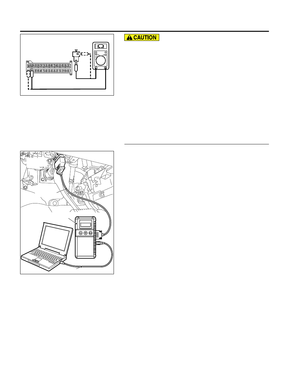
C-27 Harness side
connector (front view)
Resistor harness
side connector
Do not insert a test probe into the terminal from its front side
directly, as the connector contact pressure may be
weakened.
(3)
Check for continuity between the following terminals. It
should be less than 2 ohms.
⦆
SRS-ECU connector C-27 (terminal No.45) and the special
tool (terminal No.2)
⦆
SRS-ECU connector C-27 (terminal No.46) and the special
tool (terminal No.1)
Q:Does continuity exist?
YES:
Erase the diagnostic trouble code memory, and
recheck if any DTC set. If DTC B1C3A set, replace the SRS-
ECU (Refer to P.52B-326). Then go to Step 5.
NO:
Replace harness wires between SRS-ECU connector C-27
and driver’s seat belt pre-tensioner connector D-121.
Then go to Step 5.
STEP 5. Recheck for diagnostic trouble code.
ZC501967
AC404789
ZC5019680000
MB991824
MB991827
MB991910
Data link
connector
Check again if the DTC is set.
(1)
Erase the DTC.
(2)
Turn the ignition switch to the "ON" position.
(3)
Check if the DTC is set.
(4)
Turn the ignition switch to the "LOCK" (OFF) position.
Q:Is DTC B1C3A set?
YES:
Return to Step 1.
NO:
The procedure is complete.
SUPPLEMENTAL RESTRAINT SYSTEM (SRS)
52B-227
SRS AIR BAG DIAGNOSIS