Mitsubishi Outlander XL. Manual - part 803
STEP 1. Using scan tool MB991958, read the diagnostic
trouble code.
ZC501967
AC404789
ZC5019680000
MB991824
MB991827
MB991910
Data link
connector
To prevent damage to scan tool MB991958, always turn the
ignition switch to the "LOCK" (OFF) position before
connecting or disconnecting scan tool MB991958.
(1)
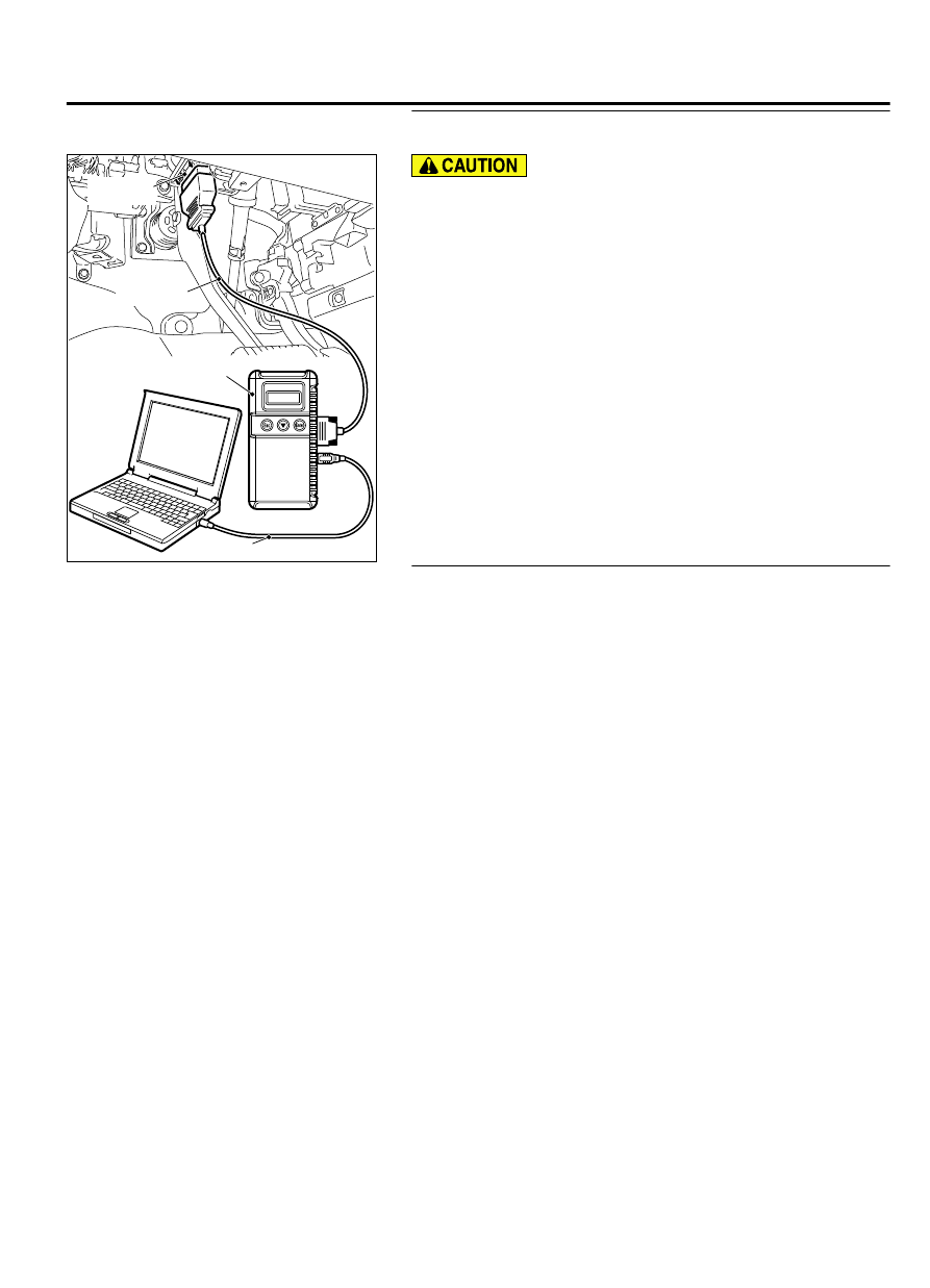
Connect scan tool MB991958. Refer to "How to connect scan
tool (M.U.T.-III) P.42B-10."
(2)
Turn the ignition switch to the "ON" position.
(3)
Check whether the KOS-ECU related DTC is set.
(4)
Turn the ignition switch to the "LOCK" (OFF) position.
Q:Is the DTC set?
YES:
Diagnose the KOS-ECU. Refer to P.42B-18.
NO:
Go to Step 2.
STEP 2. Check the customize function.
Check that either of the followings other than "Not sound tone
alarm" is set for "Tone alarm answer back" with the
customization function.
⦆
At keyless key
⦆
At keyless
⦆
At Both
Q:Is the check result normal?
YES:
Go to Step 3.
NO:
Set either of the followings other than "Not sound
tone alarm" for "Tone alarm answer back" with the
customization function (Refer to P.42B-170).
KEYLESS OPERATION SYSTEM (KOS)
42B-155
DIAGNOSIS