Mitsubishi Outlander XL. Manual - part 698
ZC601123
2
0000
1
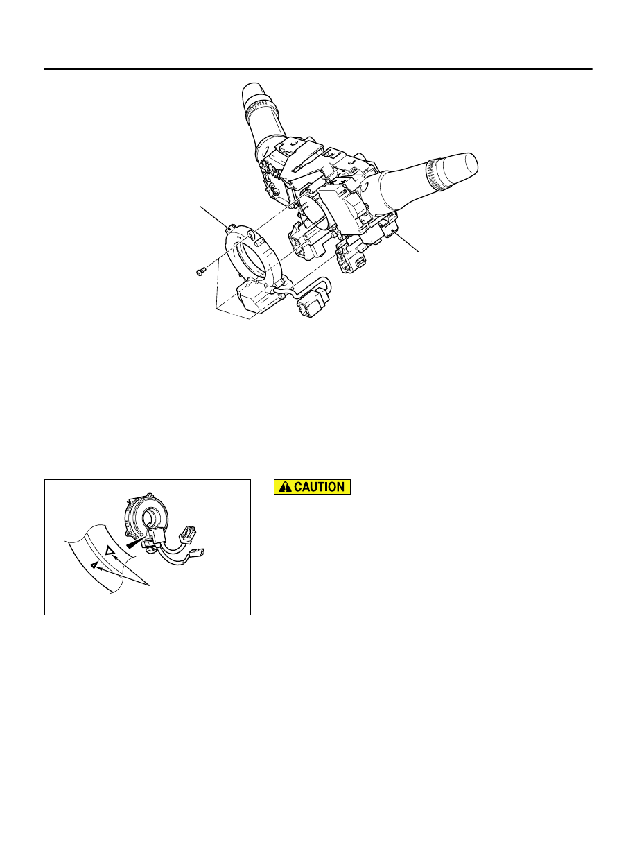
Removal steps
·
Position the front wheels in a
straight ahead direction.
>>A<<
1. Clock
spring/column
switch
assembly (Refer to GROUP 52B
- SRS Control Unit P.52B-326.)
Removal steps
>>A<<
2. Steering wheel sensor
INSTALLATION SERVICE POINTS
A NEUTRAL POSITIONING OF STEERING WHEEL SENSOR
ZC601124
Mating marks
0000
⦆
Always align the center of the clock spring before
installing the steering wheel sensor. Otherwise, the
sensor can be damaged.
⦆
If the center of the clock spring is not correctly aligned,
the steering wheel may not be turned fully or the cable
inside the clock spring may be broken, causing the SRS
air bag to be inoperative or operated incorrectly.
1.
Align the mating marks of the clock spring.
Alignment of mating marks
(1)
Turn the clock spring clockwise fully.
(2)
Turn the clock spring counterclockwise approximately
three and 3/4 turns to align the mating marks.
(3)
Install the clock spring to the column switch.
ACTIVE SKID CONTROL SYSTEM (ASC)
35C-199
STEERING WHEEL SENSOR