Mitsubishi Outlander XL. Manual - part 689


  Index      Mitsubishi     Mitsubishi Outlander XL - service repair manual 2007 year


Search            


Content   ..  687  688  689  690   ..


Mitsubishi Outlander XL. Manual - part 689


JOINT 
CONNECTOR
(CAN1)

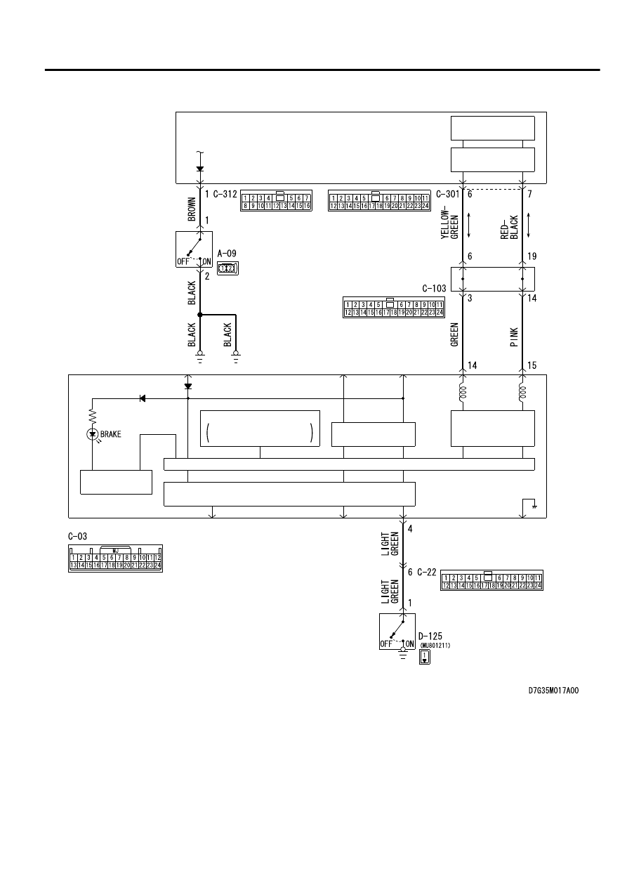
Brake Warnnig Light Circuit

INTERFACE
CIRCUIT

INTERFACE
CIRCUIT

CPU

CAN 
TRANSCEIVER 
CIRCUIT

LED DRIVE 
CIRCUIT

COMBINATION METER

PARKING
BRAKE SWITCH

LCD

FUEL WARNING/OIL 
PRESSURE WARNING

INTERFACE
CIRCUIT

CAN DRIVE
CIRCUIT

ETACS-
ECU

BRAKE FLUID
LEVEL SWITCH

CIRCUIT OPERATION
When the parking brake switch is turned ON, the combination
meter  terminal  No.  4  is  earthed,  and  the  brake  warning  light
illuminates.

ACTIVE SKID CONTROL SYSTEM (ASC)

35C-163

DIAGNOSIS

TECHNICAL DESCRIPTION (COMMENT)
The following cases may have occurred.

Ground fault in the parking brake switch circuit.

The EBD is defective.

The brake fluid level in the brake fluid reservoir is the specified
value or lower.

TROUBLESHOOTING HINTS (The most likely causes for
this case:)

Low brake fluid level

Damaged wiring harness and connectors

Parking brake switch malfunction

Combination meter malfunction

Malfunction of ETACS-ECU

Malfunction of EBD

DIAGNOSIS

Required Special Tools:

MB991958: Scan Tool (M.U.T.-III Sub Assembly)

MB991824: Vehicle Communication Interface (V.C.I.)

MB991827: M.U.T.-III USB Cable

MB991910: M.U.T.-III Main Harness A

STEP 1. Brake fluid level check

Q:Is the check result normal?

YES:

 Go to Step 2.

NO:

 Add brake fluid to the specified level.

STEP 2. Brake fluid level switch check
Refer to GROUP 35A - On-vehicle Service P.35A-19.

Q:Is the check result normal?

YES:

 Go to Step 3.

NO:

 Replace the reservoir assembly and master cylinder

assembly.

STEP 3. Voltage measurement at C-312 ETACS-ECU
connector

ZC6016860000

C-312: Harness side

Measure the voltage between the terminal No. 1 and the body
ground.

OK: Approx. 5 volts

Q:Is the check result normal?

YES:

 Go to Step 4.

NO:

 Replace ETACS-ECU.

STEP 4. Connector check: C-312 ETACS-ECU connector,
A-09 brake fluid level switch connector

Q:Is the check result normal?

35C-164

ACTIVE SKID CONTROL SYSTEM (ASC)

DIAGNOSIS

YES:

 Go to Step 5.

NO:

 Repair the defective connector.

STEP 5. Check the wiring harness between the C-312
ETACS-ECU connector terminal No. 1 and the A-09 brake
fluid level switch connector terminal No. 1.

Q:Is the check result normal?

YES:

 Go to Step 6.

NO:

 Check the wiring harness between the C-312 ETACS-ECU

connector terminal No. 1 and the A-09 brake fluid level
switch connector terminal No. 1.

STEP 6. Parking brake lever stroke check
Refer to GROUP 36 - On-vehicle Service P.36-11.

Q:Is the check result normal?

YES:

 Go to Step 7.

NO:

 Adjust the parking brake lever stroke, and then go

to Step 10.

STEP 7. Parking brake switch check
Refer to GROUP 36 - On-vehicle Service P.36-12.

Q:Is the check result normal?

YES:

 Go to Step 8.

NO:

 Replace the parking brake switch.

STEP 8. Voltage measurement at the C-03 combination
meter connector

ZC601695

C-07: Harness side

0000

Measure the voltage between terminal No. 4 and body ground.

OK: Approx. 5 volts

Q:Is the check result normal?

YES:

 Go to Step 9.

NO:

 Replace the combination meter assembly, and then go

to Step 10.

STEP 9. Connector check: C-03 Combination meter
connector, C-22 intermediate connector, D-125 parking
brake switch connector

Q:Is the check result normal?

YES:

 Repair the wiring harness between the C-03

combination meter connector terminal No. 4 and the D-125
parking brake switch connector.

NO:

 Repair the defective connector.

STEP 10. Retest the system.

Q:Does the brake warning light turn ON and OFF normally

according to the parking brake lever operation?

YES:

 The procedure is complete.

NO:

 Return to Step 1.

ACTIVE SKID CONTROL SYSTEM (ASC)

35C-165

DIAGNOSIS

Inspection Procedure 4: ABS Warning Light does not Illuminate when Ignition Switch
is Turned to the ON Position (Engine Stopped).

M13506100087USA0000010000

SYSTEM OPERATION

ASC-ECU  sends  the  illumination  request  signal  of  the  ABS
warning light to the combination meter through ETACS-ECU
via CAN communication.

ASC-ECU illuminates the ABS warning light via ETACS-ECU
for approximately 3 seconds for valve check with the ignition
switch turned to the ON position.

TECHNICAL DESCRIPTION (COMMENT)
This may be caused by faults in the CAN bus line, ETACS-ECU,
combination meter or ASC-ECU.

PROBABLE CAUSES

Damaged wiring harness and connectors

Malfunction of ETACS-ECU

Combination meter malfunction

ASC-ECU malfunction

DIAGNOSIS

Required Special Tools:

MB991958: Scan Tool (M.U.T.-III Sub Assembly)

MB991824: Vehicle Communication Interface (V.C.I.)

MB991827: M.U.T.-III USB Cable

MB991910: M.U.T.-III Main Harness A

STEP 1. M.U.T.-III CAN bus diagnostics
Use scan tool to diagnose the CAN bus lines.

Q:Is the check result normal?

YES:

 Go to Step 2.

NO:

 Repair the CAN bus lines. (Refer to GROUP 54D - CAN

Bus Diagnostics table P.54D-17.)

STEP 2. M.U.T.-III diagnostic trouble code
Use scan tool to check the diagnostic trouble code for the ASC
system.

Q:Is the diagnostic trouble code set?

YES:

 Carry out the diagnosis for the diagnostic trouble

code. (Refer to P.35C-11.)

NO:

 Go to Step 3.

STEP 3. M.U.T.-III actuator test
Perform  the  actuator  test  No.  07  of  the  combination  meter
system, and check if the ABS warning light illuminates.

35C-166

ACTIVE SKID CONTROL SYSTEM (ASC)

DIAGNOSIS


Content   ..  687  688  689  690   ..