Mitsubishi Outlander XL. Manual - part 630


  Index      Mitsubishi     Mitsubishi Outlander XL - service repair manual 2007 year


Search            


Content   ..  628  629  630  631   ..


Mitsubishi Outlander XL. Manual - part 630


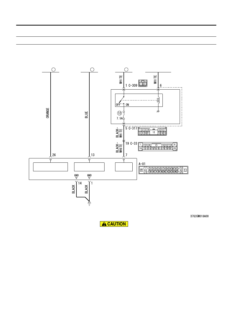
DTC C2104: Faulty valve power supply circuit

M13502000935USA0000010000

Power Supply Circuit

ETACS-
ECU

POWER
SUPPLY

ABS-ECU

FUSIBLE
LINK

34

IG1
RELAY

FUSIBLE
LINK

27

FUSIBLE
LINK

26

SOLENOID VALVE
POWER SUPPLY

MOTOR POWER
SUPPLY

IGNITION
SWITCH (IG1)

If there is any problem in the CAN bus lines, an incorrect
diagnostic trouble code may be set. Prior to this diagnosis,
diagnose the CAN bus lines. (Refer to GROUP 54D, Trouble
code diagnosis P.54D-17).

CIRCUIT OPERATION

ABS-ECU contains the power supply circuit (terminal No. 26)
for the solenoid valve. The solenoid valve is energized by the
valve relay, which is incorporated in ABS-ECU.

ANTI-LOCK BRAKING SYSTEM (ABS)

35B-83

ANTI-LOCK BRAKING SYSTEM (ABS) DIAGNOSIS

The valve relay, which is incorporated in ABS-ECU, is always
energizing  the  solenoid  valve  unless  the  initial  check  is  in
progress when the ignition switch is turned on, or the recurrent
system check is in progress.

DTC SET CONDITIONS
This diagnostic trouble codes will be set under the cases below:

When  the  solenoid  valve  supply  voltage  is  not  within  the
standard value.

PROBABLE CAUSES

Current trouble

Fusible link malfunction

Damaged wiring harness and connectors

Abnormality in battery or generator

ABS-ECU malfunction

Past trouble

Carry  out  diagnosis  with  particular  emphasis  on  wiring
harness  and  connector  failures  between  the  power  supply
circuit (terminal No. 26) to ABS-ECU solenoid valve or ground
circuit (terminal No. 1). For diagnosis procedures, refer to How
to treat past trouble (Refer to GROUP 00 - How to Cope with
Intermittent Malfunction P.00-15).

DIAGNOSIS

Required Special Tools:

MB991958: Scan Tool (M.U.T.-III Sub Assembly)

MB991824: Vehicle Communication Interface (V.C.I.)

MB991827: M.U.T.-III USB Cable

MB991910: M.U.T.-III Main Harness A

MB991974: ABS check harness

STEP 1. M.U.T.-III CAN bus diagnostics
Use scan tool to diagnose the CAN bus lines.

Q:Is the check result normal?

YES:

 Go to Step 3.

NO:

 Repair the CAN bus lines. (Refer to GROUP 54D - CAN

Bus Diagnostics table P.54D-17.) On completion, go to
Step 2.

STEP 2. Diagnostic Trouble code recheck after resetting
CAN bus lines

Q:Is DTC C2104 set?

YES:

 Go to Step 3.

NO:

 The procedure is complete.

STEP 3. Fusible link check: Check the fusible link No. 27.
Visually check for open circuit in the fusible link No. 27.

35B-84

ANTI-LOCK BRAKING SYSTEM (ABS)

ANTI-LOCK BRAKING SYSTEM (ABS) DIAGNOSIS

Q:Is the check result normal?

YES:

 Go to Step 4.

NO:

 Replace the fusible link No. 27.

STEP 4. Battery check
Refer to GROUP 54Aa - Battery Test P.54Aa-3.

Q:Is the battery in good condition?

YES:

 Go to Step 5.

NO:

 Charge or replace the battery.

STEP 5. Charging system check
Refer to GROUP 16a - Output Current Test P.16a-8.

Q:Is the charging system in good condition?

YES:

 Go to Step 6.

NO:

 Repair or replace the charging system component(s).

STEP 6. Voltage measurement at the A-01 ABS-ECU
connector

ZC601293 0024

ABS-ECU

MB991974

Check harness

A-01 ABS-ECU 
harness connector

(1)

Disconnect the connector, connect special tool MB991974 to
the harness-side connector, and measure the voltage at the
special tool connector side.

NOTE: 

Do not connect the special tool MB991974 to ABS-

ECU.

(2)

Turn the ignition switch to the ON position.

(3)

Measure the voltage between the terminal No. 26 and the
body ground.

OK: 12 volts (Battery voltage)

Q:Is the check result normal?

YES:

 Go to Step 8.

NO:

 Go to Step 7.

STEP 7. Connector check: A-01 ABS-ECU connector

Q:Is the check result normal?

YES:

 The open or short circuit may be present in the

power supply circuit. Repair the wiring harness between
the A-01 ABS-ECU connector terminal No. 26 and the fusible
link No. 27.

NO:

 Repair the defective connector.

ANTI-LOCK BRAKING SYSTEM (ABS)

35B-85

ANTI-LOCK BRAKING SYSTEM (ABS) DIAGNOSIS

STEP 8. Resistance measurement at A-01 ABS-ECU
connector

ZC601293 0025

Check harness

ABS-ECU

MB991974

A-01 ABS-ECU 
harness connector

(1)

Disconnect the connector, connect special tool MB991974 to
the harness-side connector, and measure the voltage at the
special tool connector side.

NOTE: 

Do not connect the special tool MB991974 to ABS-

ECU.

(2)

Resistance between the terminal No. 1 and the body ground

OK: Continuity exists (2 ohms or less)

Q:Is the check result normal?

YES:

 Go to Step 10.

NO:

 Go to Step 9.

STEP 9. Connector check: A-01 ABS-ECU connector

Q:Is the check result normal?

YES:

 An open circuit may be present in the ground

circuit. Repair the wiring harness between the A-01 ABS-
ECU connector terminal No. 14 and the body ground.

NO:

 Repair the defective connector.

STEP 10. Check whether the diagnostic Trouble code is
reset.

Q:Is DTC C2104 set?

YES:

 Replace the ABS-ECU.

NO:

 Intermittent malfunction. (Refer to GROUP 00 - How

to Cope with Intermittent Malfunction P.00-15.)

35B-86

ANTI-LOCK BRAKING SYSTEM (ABS)

ANTI-LOCK BRAKING SYSTEM (ABS) DIAGNOSIS


Content   ..  628  629  630  631   ..