Mitsubishi Outlander XL. Manual - part 616


  Index      Mitsubishi     Mitsubishi Outlander XL - service repair manual 2007 year


Search            


Content   ..  614  615  616  617   ..


Mitsubishi Outlander XL. Manual - part 616


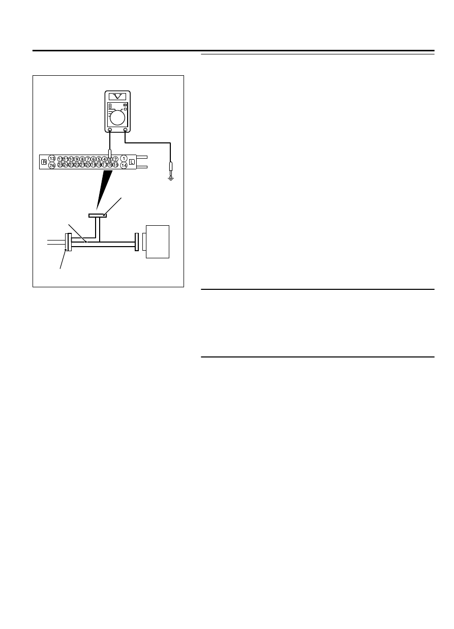
STEP 4. Voltage measurement at the A-01 ABS-ECU
connector

ZC601293 0022

ABS-ECU

MB991974

Check harness

A-01 ABS-ECU 
harness connector

(1)

Disconnect  the  ABS-ECU  connector,  connect  special  tool
MB991974 to the harness-side connector, and then measure
the resistance at the special tool connector side.

NOTE: 

Do not connect the special tool MB991974 to ABS-

ECU.

(2)

Turn the ignition switch to the ON position.

(3)

Measure the voltage between the wheel speed sensor power
supply terminal (signal terminal) No. 16/the ground terminal
No. 15 and the body ground.

OK: 0 volt

Q:Is the check result normal?

YES:

 Go to Step 5.

NO (Not normal at the terminal No. 16 or 15):

 Go to Step

7.

STEP 5. Connector check: A-01 ABS-ECU connector, C-129
intermediate connector, D-133 wheel speed sensor <RR>
connector

Q:Is the check result normal?

YES:

 Go to Step 6.

NO:

 Repair the defective connector.

STEP 6. Wiring harness check between A-01 ABS-ECU
connector terminal No. 16/15 and D-133 wheel speed sensor
<RR> connector terminal No. 1/2

Check for short circuit in wheel speed sensor <RR> circuit

Q:Is the check result normal?

YES:

 Replace the wheel speed sensor <RR>.

NO:

 Repair the wiring harness.

ANTI-LOCK BRAKING SYSTEM (ABS)

35B-27

ANTI-LOCK BRAKING SYSTEM (ABS) DIAGNOSIS

STEP 7. Resistance measurement at A-01 ABS-ECU
connector

ZC601293 0023

Check harness

ABS-ECU

MB991974

A-01 ABS-ECU 
harness connector

(1)

Disconnect  the  ABS-ECU  connector,  connect  special  tool
MB991974 to the harness-side connector, and then measure
the resistance at the special tool connector side.

NOTE: 

Do not connect the special tool MB991974 to ABS-

ECU.

(2)

Resistance between the wheel speed sensor power supply
terminal (signal terminal) No. 16/the ground terminal No. 15
and the body ground

OK: No continuity

Q:Is the check result normal?

YES:

 Go to Step 10.

NO (Not normal at the terminal No. 16 or 15):

 Go to Step

8.

STEP 8. Connector check: A-01 ABS-ECU connector, D-133
wheel speed sensor <RR> connector

Q:Is the check result normal?

YES:

 Go to Step 9.

NO:

 Repair the defective connector.

STEP 9. Wiring harness check between A-01 ABS-ECU
connector terminal No. 16/15 and D-133 wheel speed sensor
<RR> connector terminal No. 1/2

Check for short circuit in wheel speed sensor <RR> circuit

Q:Is the check result normal?

YES:

 Replace the wheel speed sensor <RR>.

NO:

 Repair the wiring harness.

35B-28

ANTI-LOCK BRAKING SYSTEM (ABS)

ANTI-LOCK BRAKING SYSTEM (ABS) DIAGNOSIS

STEP 10. Voltage measurement at the A-01 ABS-ECU
connector

ZC601292 0009

ABS-ECU

MB991974

Check harness

A-01 ABS-ECU 
harness connector

(1)

Disconnect  the  ABS-ECU  connector,  connect  special  tool
MB991974  to  the  ABS-ECU-side  connector  and  harness-
side connector, and then measure the voltage at the special
tool connector side.

(2)

Turn the ignition switch to the ON position.

(3)

Measure the voltage between the wheel speed sensor circuit
power supply terminal (signal terminal) No. 16 and the body
ground.

OK: Approximately battery voltage

Q:Is the check result normal?

YES:

 Go to Step 13.

NO:

 Go to Step 11.

STEP 11. Connector check: A-01 ABS-ECU connector,
D-133 wheel speed sensor <RR> connector

Q:Is the check result normal?

YES:

 Go to Step 12.

NO:

 Repair the defective connector.

STEP 12. Wiring harness check between A-01 ABS-ECU
connector terminal No. 16/15 and D-133 wheel speed sensor
<RR> connector terminal No. 1/2

Check for open circuit in wheel speed sensor <RR> circuit

Q:Is the check result normal?

YES:

 Replace the wheel speed sensor.

NO:

 Repair the wiring harness.

STEP 13. Check for wheel speed sensor as a single unit
Refer to P.35B-155.

Q:Is the check result normal?

YES:

 Go to Step 14.

NO:

 Replace the wheel speed sensor.

STEP 14. Check whether the diagnostic trouble code is
reset.

(1)

Erase the diagnostic trouble code.

(2)

Drive the vehicle at 12mph (20 km/h) or more.

NOTE: 

The ABS warning light does not turn OFF in some

cases unless the vehicle runs at 12mph (20 km/h) or
higher.

ANTI-LOCK BRAKING SYSTEM (ABS)

35B-29

ANTI-LOCK BRAKING SYSTEM (ABS) DIAGNOSIS

Q:Is DTC C102B set?

YES:

 Replace the ABS-ECU.

NO:

 Intermittent malfunction (Refer to GROUP 00 - How to

Cope with Intermittent Malfunction P.00-15).

DTC C1011: Abnormality in FL wheel speed sensor signal

M13502000911USA0000010000

Wheel Speed Sensor Circuit

ABS-ECU

(LH)

(LH)

(RH)

(RH)

FRONT WHEEL SPEED SENSOR

REAR WHEEL SPEED SENSOR

If there is any problem in the CAN bus lines, an incorrect
diagnostic trouble code may be set. Prior to this diagnosis,
diagnose the CAN bus lines. (Refer to GROUP 54D, Trouble
code diagnosis P.54D-17
).

CIRCUIT OPERATION

The  wheel  speed  sensor  is  a  kind  of  a  pulse  generator.  It
consists of encoders (a plate on which north and south pole
sides of the magnets are arranged alternately) for detecting
the  wheel  speed  which  rotates  at  the  same  speed  of  the
wheels  and  wheel  speed  sensors.  This  sensor  outputs
frequency pulse signals in proportion to the wheel speed.

The pulse signals, which the wheel speed sensor creates, are
sent to ABS-ECU. ABS-ECU uses the frequency of the pulse
signals to determine the wheel speed.

35B-30

ANTI-LOCK BRAKING SYSTEM (ABS)

ANTI-LOCK BRAKING SYSTEM (ABS) DIAGNOSIS


Content   ..  614  615  616  617   ..