Mitsubishi Outlander XL. Manual - part 596


  Index      Mitsubishi     Mitsubishi Outlander XL - service repair manual 2007 year


Search            


Content   ..  594  595  596  597   ..


Mitsubishi Outlander XL. Manual - part 596


ZC6003540000

5

3

4

1

2

39 ± 6 N·m
29 ± 4 ft-lb

2

2

2

2

2

2

71 ± 10 N·m
52 ± 2 ft-lb

1

1

71 ± 10 N·m
52 ± 2 ft-lb

1

1

71 ± 10 N·m
52 ± 2 ft-lb

1

1

71 ± 10 N·m
52 ± 2 ft-lb

1

1

71 ± 10 N·m
52 ± 2 ft-lb

2

2

9

7

6

8

2

2

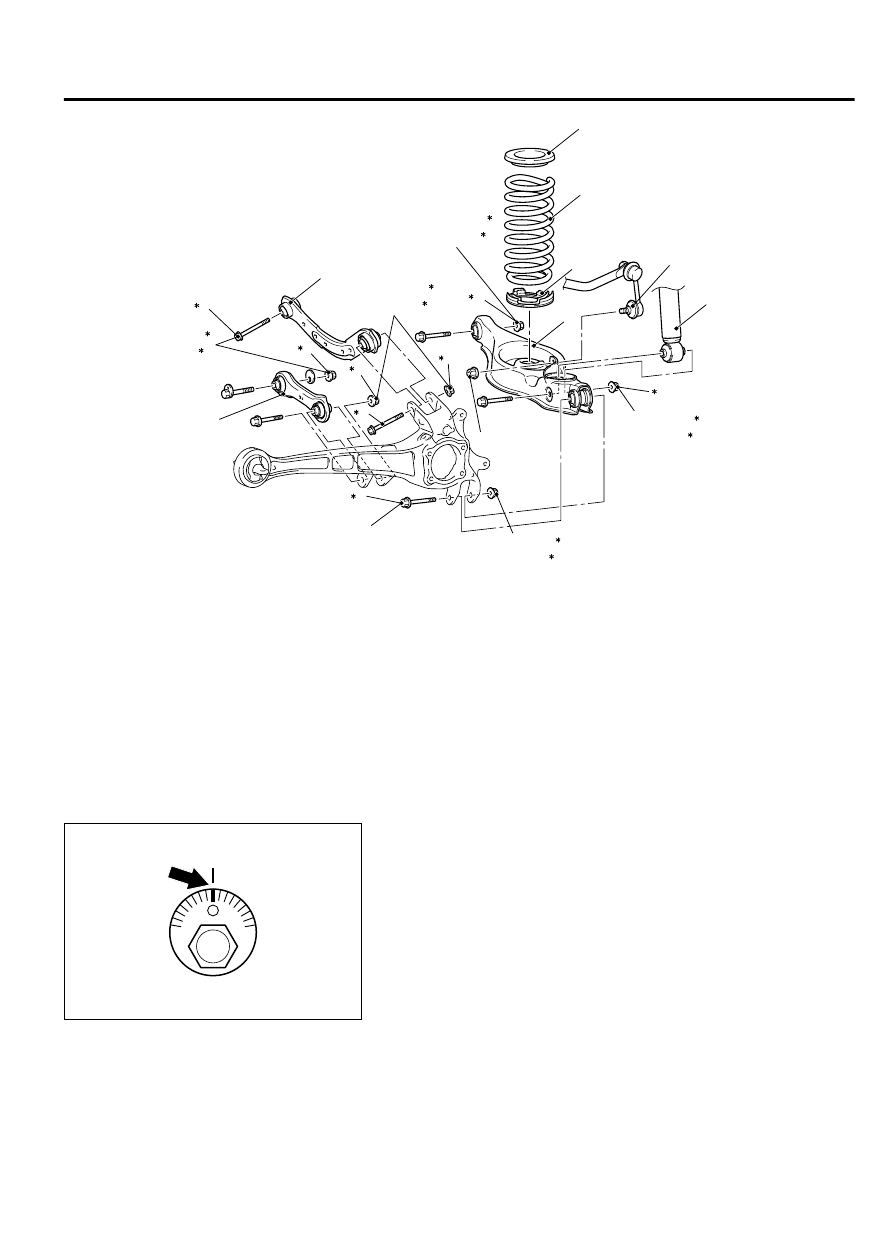
Control link and upper arm removal

<<A>>

1.

Control link

>>A<<

2.

Upper arm
Lower arm removal steps

3.

Stabilizer link connection

4.

Lower arm and trailing arm connection

5.

Shock absorber connection

Lower arm removal steps

6.

Coil spring

7.

Coil spring upper pad

8.

Coil spring lower pad

9.

Lower arm

REMOVAL SERVICE POINTS

<<A>> CONTROL LINK REMOVAL

ZC3055560000

Mating mark

Make a mating mark on the toe adjusting bolt, and remove the
control link.

REAR SUSPENSION

34-11

CONTROL LINK, UPPER ARM AND LOWER ARM

INSTALLATION SERVICE POINTS

>>A<< UPPER ARM INSTALLATION

ZC3055600000

Install the upper arm so that the hole faces the body side.

LOWER ARM BUSHING REPLACEMENT

M13401000118USA0000010000

Required Special Tools:

MB992123: Arm Bushing Remover and Installer

MB991448: Bushing Remover and Installer Base

MB991449: Bushing Remover and Installer Supporter

As the bushing has different outer diameters at both ends,
be  careful  not  to  confuse  the  removal  direction  with  the
press-fit direction.

ZC3057550000

MB992123

MB991449

MB991448

Driving Out

Lower arm

Use the special tools MB992123, MB991448 and MB991449 to
remove and press-fit the lower arm bushing.

34-12

REAR SUSPENSION

CONTROL LINK, UPPER ARM AND LOWER ARM

ZC3057540000

MB991449

MB992123

MB991448

Lower arm

Press-Fitting

TRAILING ARM ASSEMBLY

REMOVAL AND INSTALLATION

M13401000042USA0000010000

The parts indicated by*1should be temporarily
tightened,  and  then  fully  tightened  with  the
vehicle  standing  on  the  ground  and  the  curb
weight condition.

The parts indicated by*2are the bolts/nuts with
friction coefficient stabilizer. In removal, ensure

there is no damage, clean dust and soiling from
the  bearing  and  thread  surfaces,  and  tighten
them to the specified torque.

The  part  indicated  by*3is  the  bolt/nut  with
friction  coefficient  stabilizer.  In  removal,
replace it with new one.

Pre-removal operation

Brake  Fluid  Draining  (Refer  to  GROUP  35A,  On-vehicle

Service-  Brake  Fluid  Level  Inspection  and  Bleeding  P.

35A-18.)

Height  Sensor  and  Control  Link  Disconnection  (Refer  to

GROUP  54Ac,  Headlight  Automatic  Leveling  System  P.

54Ac-179.)

Post-installation operation

Height  Sensor  and  Control  Link  Connection  (Refer  to

GROUP  54Ac,  Headlight  Automatic  Leveling  System  P.

54Ac-179.)

Brake  Fluid  Refilling  and  Bleeding  (Refer  to  GROUP  35A,

On-vehicle  Service-  Brake  Fluid  Level  Inspection  and

Bleeding P.35A-18.)

Wheel Alignment Check and Adjustment (Refer to P.34-9.)

Parking Brake Lever Stroke Check and Adjustment (Refer to

GROUP 36, On-vehicle Service - Parking Brake Lever Stroke

Check and Adjustment P.36-11.)

REAR SUSPENSION

34-13

TRAILING ARM ASSEMBLY

ZC6003590000

71 ± 10 N·m
52 ± 7 ft-lb

110 ± 11 N·m
81 ± 8 ft-lb

2

95 ± 14 N·m
70 ± 10 ft-lb

1

1

N

3

8.5 ± 1.5 N·m
76 ± 13 in-lb

3

1

2

9

4

7

5

6

8

10

11

12

13

11 ± 2 N·m
98 ± 17 in-lb

2

2

2

2

1

55 ± 5 N·m
41 ± 3 ft-lb

11 ± 2 N·m
98 ± 17 in-lb

71 ± 10 N·m
52 ± 7 ft-lb

1

1

39 ± 6 N·m
29 ± 4 ft-lb

71 ± 10 N·m
52 ± 7 ft-lb

1

1

2

11 ± 2 N·m
98 ± 17 in-lb

1

<FWD>

Removal steps

1.

Rear wheel speed sensor

2.

Hose clip

3.

Brake hose bracket

<<B>>

4.

Caliper assembly

5.

Brake disc

6.

Rear hub assembly

7.

Parking brake cable connecting bolt

Removal steps

<<C>>

8.

Rear brake assembly

9.

Control link connection

10. Stabilizer link connection
11. Lower arm connection
12. Upper arm connection
13. Trailing arm assembly


34-14

REAR SUSPENSION

TRAILING ARM ASSEMBLY


Content   ..  594  595  596  597   ..