Mitsubishi Outlander XL. Manual - part 547
ZC5019600000
C
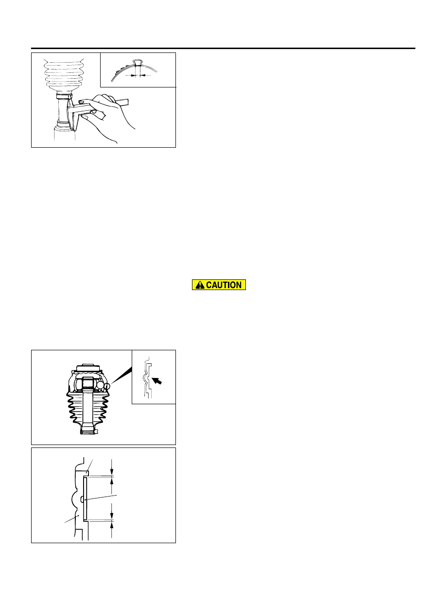
8.
Check that the crimping amount (C) of the boot band is at the
standard value.
Standard value (C): 2.4 - 2.8 mm (0.10 - 0.11 inch)
If the crimping amount is larger than 2.8 mm (0.11
inch)
Readjust the value of (W) in step 5 according to the
following formula, and then repeat the operation in
step 7.
W = 5.5 mm (0.22 inch) - C
Example: If C = 2.9 mm (0.11 inch), then W = 2.6 mm
(0.10 inch)
If the crimping amount is smaller than 2.4 mm (0.10
inch)
Remove the EBJ boot band, readjust the value of
(W) in step 5 according to the following formula,
and then repeat the operations in steps 6 and 7
using a new EBJ boot band.
W = 5.5 mm (0.22 inch) - C
Example: If C = 2.3 mm (0.09 inch), then W = 3.2 mm
(0.13 inch)
9.
Check that the boot band is not sticking out past the place
where it has been installed. If the boot band is sticking out,
remove it and then repeat steps 6 to 8, using a new boot band.
The driveshaft joint uses special grease. Do not mix old and
new or different types of grease.
10.
Fill the inside of the boot with the specified amount of the
specified grease.
Specified grease: Repair kit grease
Amount to use: 140 ± 10 g (4.9 ± 0.3 ounces)
ZC5019610000
11.
Align the center groove on the EBJ boot big end with the EBJ
case groove.
12.
Follow the same procedure as in step 5 to adjust the size of
the opening (W) on the special tool so that it is at the standard
value.
Standard value (W): 3.2 mm (0.13 inch)
ZC5019620000
Boot
Projection
Boot band
(large)
D
E
13.
Position the EBJ boot band (large) so that there is even
clearance at either end (D and E).
14.
Use special tool MB991561 to crimp the EBJ boot band
(large) in the same way as in step 7.
FRONT AXLE
26-35
DRIVESHAFT ASSEMBLY