Mitsubishi Outlander XL. Manual - part 492
 

  Index      Mitsubishi     Mitsubishi Outlander XL - service repair manual 2007 year


Search            


Content   ..  490  491  492  493   ..


Mitsubishi Outlander XL. Manual - part 492


STEP 6. Check the TCM and A/T control solenoid valve
assembly connector pin terminals and the connection
status.

Q:Is the check result normal?

YES:

 Replace the TCM.

NO:

 Repair or replace the failure section.

STEP 7. Erase the DTC code, and drive the vehicle for a
while.
Check that the normal code is displayed.

Q:Is the check result normal?

YES:

 The procedure is complete.

NO:

 Return to START.

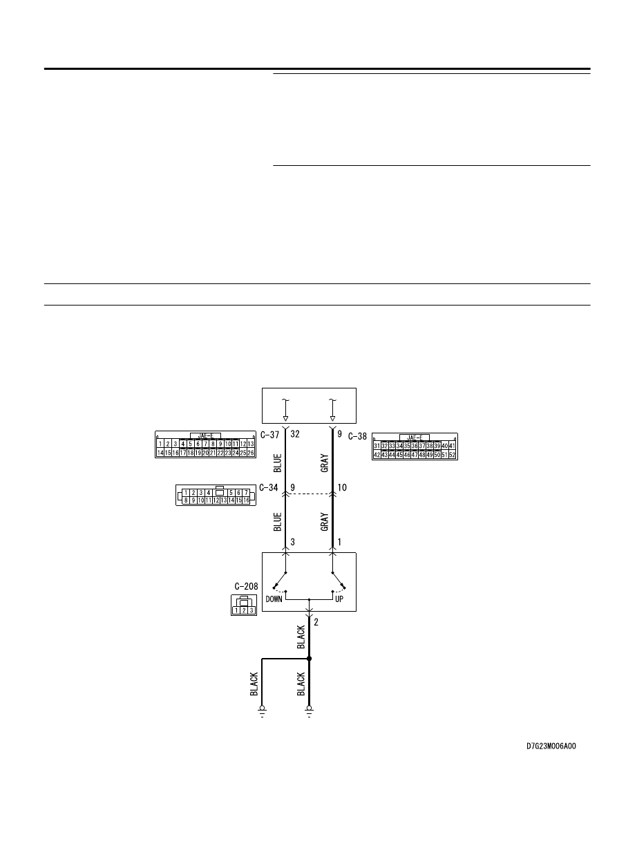
DTC P0815: Paddle Shift Switch (Up) System

M12301000415USA0000010000

PADDLE
SHIFT
SWITCH

TRANSMISSION
CONTROL
MODULE

ZC602377AA00

Paddle shift switch system circuit

AUTOMATIC TRANSAXLE MECHANICAL

23A-83

AUTOMATIC TRANSAXLE DIAGNOSIS

ZC6008750023

Connector: C-34

C-34 (BR)

ZC6035780002

Connectors: C-37, 38

C-38

C-37

Brake pedal


ZC6008770008

Connector: C-208


DESCRIPTIONS OF MONITOR METHODS

⦆

With the ignition switch ON, the paddle shift switch
(up) status continues for 60 seconds.

TROUBLESHOOTING HINTS (THE MOST LIKELY
CAUSES FOR THIS CODE TO BE SET ARE:)

⦆

Malfunction of the Paddle shift switch (up) system
circuit

⦆

Damaged harness or connector

⦆

Malfunction of the TCM

⦆

Malfunction of the paddle shift switch


DIAGNOSIS

STEP 1. Check the TCM terminal voltage.
[C-38 TCM connector (vehicle side, connected)]
Measure the voltage between C-38 No. 9 and body ground.

⦆

Ignition switch: ON

⦆

Paddle (ON) operated: 1V or less

⦆

Other than above: battery positive voltage

Q:Is the check result normal?

YES:

 Go to Step 2.

NO:

 Go to Step 3.

STEP 2. Check the TCM connector, vehicle-side wiring
harness connector pin terminal, and the connection status.

Q:Is the check result normal?

YES:

 Go to Step 6.

23A-84

AUTOMATIC TRANSAXLE MECHANICAL

AUTOMATIC TRANSAXLE DIAGNOSIS

NO:

 Repair or replace the failure section.

STEP 3. Check between the TCM connector and the paddle
shift switch (up).
Check for continuity between C-38 TCM connector terminal No.
9 and C-208 paddle shift switch (up).

⦆

Between  C-38  terminal  No.  9  and  C-208  terminal  No.  1:
Continuity exists.

When the continuity check result is OK, check that the wiring
harness is not shorted to the body and other wiring harness.

Q:Is the check result normal?

YES:

 Go to Step 4.

NO:

 Repair or replace the failure section.

STEP 4. Check the paddle shift switch (up).
Refer to P.23A-161.

Q:Is the check result normal?

YES:

 Go to Step 5.

NO:

 Repair or replace the failure section.

STEP 5. Check the TCM connector, vehicle-side wiring
harness connector pin terminal, and the connection status.

Q:Is the check result normal?

YES:

 Replace the TCM.

NO:

 Repair or replace the failure section.

STEP 6. Erase the DTC code, and drive the vehicle for a
while.
Check that the normal code is displayed.

Q:Is the check result normal?

YES:

 The procedure is complete.

NO:

 Return to START.

DTC P0816: Paddle Shift Switch (Down) System

M12301000416USA0000010000

PADDLE SHIFT SWITCH (DOWN) SYSTEM
CIRCUIT
Refer to P.23A-83.


DESCRIPTIONS OF MONITOR METHODS

⦆

With the ignition switch ON, the paddle shift switch
(down) status continues for 60 seconds.

TROUBLESHOOTING HINTS (THE MOST LIKELY
CAUSES FOR THIS CODE TO BE SET ARE:)

⦆

Malfunction  of  the  Paddle  shift  switch  (down)
system circuit

⦆

Damaged harness or connector

⦆

Malfunction of the TCM

⦆

Malfunction of the paddle shift switch


AUTOMATIC TRANSAXLE MECHANICAL

23A-85

AUTOMATIC TRANSAXLE DIAGNOSIS

DIAGNOSIS

STEP 1. Check the TCM terminal voltage.
[C-38 TCM connector (vehicle side, connected)]
Measure the voltage between C-38 terminal No. 32 and body
ground.

⦆

Ignition switch: ON

⦆

Paddle (ON) operated: 1V or less

⦆

Other than above: battery positive voltage

Q:Is the check result normal?

YES:

 Go to Step 2.

NO:

 Go to Step 3.

STEP 2. Check the TCM connector, vehicle-side wiring
harness connector pin terminal, and the connection status.

Q:Is the check result normal?

YES:

 Go to Step 6.

NO:

 Repair or replace the failure section.

STEP 3. Check between the TCM connector and the paddle
shift switch (down).
Check for continuity between C-38 TCM connector and C-208
paddle shift switch (down).

⦆

Between  C-38  terminal  No.  32  and  C-208  terminal  No.  3:
Continuity exists.

When the continuity check result is OK, check that the wiring
harness is not shorted to the body and other wiring harness.

Q:Is the check result normal?

YES:

 Go to Step 4.

NO:

 Repair or replace the failure section.

STEP 4. Check the paddle shift switch (down).
Refer to P.23A-161.

Q:Is the check result normal?

YES:

 Go to Step 5.

NO:

 Repair or replace the failure section.

STEP 5. Check the TCM connector, vehicle-side wiring
harness connector pin terminal, and the connection status.

Q:Is the check result normal?

YES:

 Replace the TCM.

NO:

 Repair or replace the failure section.

STEP 6. Erase the DTC code, and drive the vehicle for a
while.
Check that the normal code is displayed.

Q:Is the check result normal?

YES:

 The procedure is complete.

NO:

 Return to START.

23A-86

AUTOMATIC TRANSAXLE MECHANICAL

AUTOMATIC TRANSAXLE DIAGNOSIS


Content   ..  490  491  492  493   ..