Mitsubishi Outlander XL. Manual - part 482


  Index      Mitsubishi     Mitsubishi Outlander XL - service repair manual 2007 year


Search            


Content   ..  480  481  482  483   ..


Mitsubishi Outlander XL. Manual - part 482


ZC6008720001

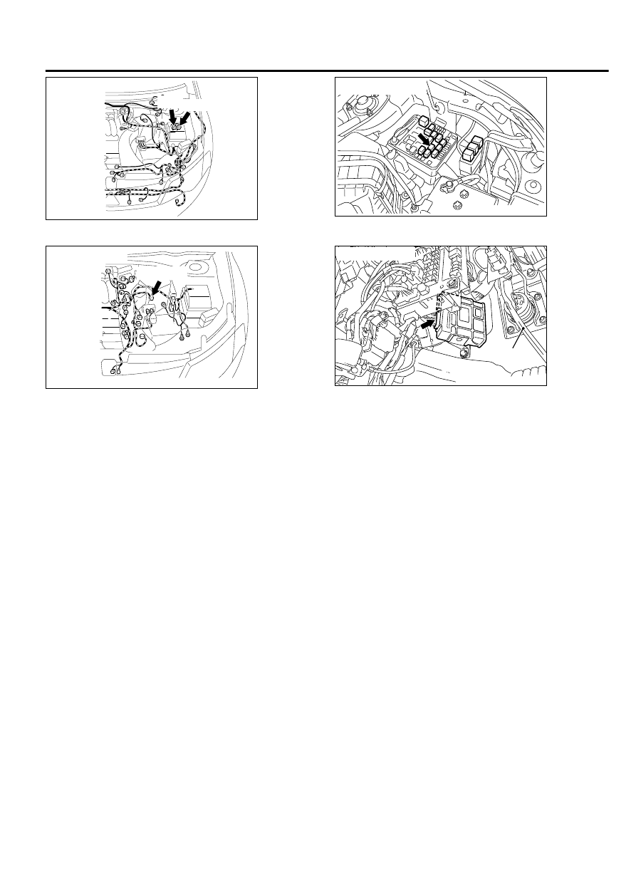
Connectors: A-12, 13

A-12 A-13

ZC6028630000

Connector: A-18X


ZC6008740002

Connector: B-108

B-108 (B)

ZC6035780000

Connector: C-37

Brake pedal


DESCRIPTIONS OF MONITOR METHODS

With the vehicle speed more than 20 km/h (12 mph),
the TCM receives no input signal from the output
shaft speed sensor.

MONITOR EXECUTION

Continuous

MONITOR EXECUTION CONDITIONS (OTHER
MONITOR AND SENSOR)

Other Monitor (There is no temporary DTC stored in
memory for the item monitored below)

Not applicable

Sensor (The sensor below is determined to be
normal)

Not applicable

AUTOMATIC TRANSAXLE MECHANICAL

23A-43

AUTOMATIC TRANSAXLE DIAGNOSIS

LOGIC FLOW CHARTS (Monitor Sequence)

Good

V

PG-B

 : Calculated Vehicle speed

          by output shaft speed sensor

START

Rapid V

PG-B

 change <

            -20 km/h/50 msec

V

PG-B

 > 20 km/h

END

Yes

No

No

Malfunction

ZC604067

Yes

Continuous failure  
       for 2 secs.

Yes

No

0000

DTC SET CONDITIONS

Check Conditions

Vehicle speed: more than 20 km/h (12 mph).

Judgement Criteria

Rapid  vehicle  speed  change:  less  than  -20  km/h/
0.05 second. (2 seconds)

OBD-II DRIVE CYCLE PATTERN
Start the engine, and drive for 5 seconds, with 1st gear
fixed (1st gear in sport mode), at more than 20 km/h
(12  mph)  with  more  than  50%  of  throttle  valve
opening. Then stop the vehicle, and drive again for 5

seconds, with 1st gear fixed (1st gear in sport mode),
at more than 20 km/h (12 mph) with more than 50%
of throttle valve opening.

TROUBLESHOOTING HINTS (THE MOST LIKELY
CAUSES FOR THIS CODE TO BE SET ARE:)

Malfunction  of  the  output  shaft  speed  sensor
system circuit

Damaged harness or connector

Malfunction of the output shaft speed sensor

Malfunction of the TCM

Malfunction of the output shaft speed sensor rotor
(A/T assembly)


DIAGNOSIS

STEP 1. Check the TCM terminal voltage and frequency.
[C-37 TCM connector (vehicle side, connected)]

23A-44

AUTOMATIC TRANSAXLE MECHANICAL

AUTOMATIC TRANSAXLE DIAGNOSIS

Check that the voltage between C-37 terminal No. 48 and C-38
terminal No. 13 or C-38 terminal No. 26 is 0 V, and then check
the frequency of C-37 terminal No. 37.

At D range, vehicle speed is 30 km/h (19 mph): Approx. 588
Hz

Q:Is the check result normal?

YES:

 Go to Step 6.

NO:

 Go to Step 2.

STEP 2. Check the power supply and sensor ground.
[B-108  output  shaft  speed  sensor  connector  (vehicle  side,
disconnected)]

With the ignition switch ON: Terminal No. 1 to No. 3 → Battery
positive voltage

Q:Is the check result normal?

YES:

 Go to Step 3.

NO:

 Go to Step 4.

STEP 3. Check the wiring harness between the output shaft
speed sensor and TCM.
Check for continuity between B-108 output shaft speed sensor
terminals and C-37 TCM terminals.

Between  B-108  terminal  No.  2  and  C-37  terminal  No.  37:
Continuity exists.

When the continuity check result is OK, check that the wiring
harness is not shorted to the body and other wiring harness.

Q:Is the check result normal?

YES:

 Replace the output shaft speed sensor with the one

of the same transaxle of the same model. Then go to Step
7.

NO:

 Repair or replace the failure section, and then go

to Step 6.

STEP 4. Check the path between the ignition switch and the
output shaft speed sensor.

Check the wiring harness for an open/short circuit between the
ignition switch and B-108 output shaft speed sensor connector
terminal No. 1.

Check for a blown fuse.

Q:Is the check result normal?

YES:

 Go to Step 5.

NO:

 Repair or replace the failure section.

STEP 5. Check the wiring harness between the output shaft
speed sensor and TCM.
Check for continuity between B-108 output shaft speed sensor
terminals and C-38 TCM terminals.

Between  B-108  terminal  No.  3  and  C-37  terminal  No.  48:
Continuity exists.

When the continuity check result is OK, check that the wiring
harness is not shorted to the body and other wiring harness.

Q:Is the check result normal?

AUTOMATIC TRANSAXLE MECHANICAL

23A-45

AUTOMATIC TRANSAXLE DIAGNOSIS

YES:

 Go to Step 8.

NO:

 Repair or replace the failure section.

STEP 6. Drive the vehicle for a while.
Check that the normal code is displayed.

Q:Is the check result normal?

YES:

 The procedure is complete.

NO:

 Replace the TCM.

STEP 7. After replacing the output shaft speed sensor, drive
the vehicle for a while, and then check the DTC again.

Q:Is the check result normal?

YES:

 Replace the output shaft speed sensor.

NO:

 Replace the TCM.

STEP 8. Check the TCM connector pin terminal and the
connection status.

Q:Is there a failure point?

YES:

 Repair or replace the failure section.

NO:

 Replace the TCM.

23A-46

AUTOMATIC TRANSAXLE MECHANICAL

AUTOMATIC TRANSAXLE DIAGNOSIS


Content   ..  480  481  482  483   ..