Mitsubishi Outlander XL. Manual - part 316


  Index      Mitsubishi     Mitsubishi Outlander XL - service repair manual 2007 year


Search            


Content   ..  314  315  316  317   ..


Mitsubishi Outlander XL. Manual - part 316


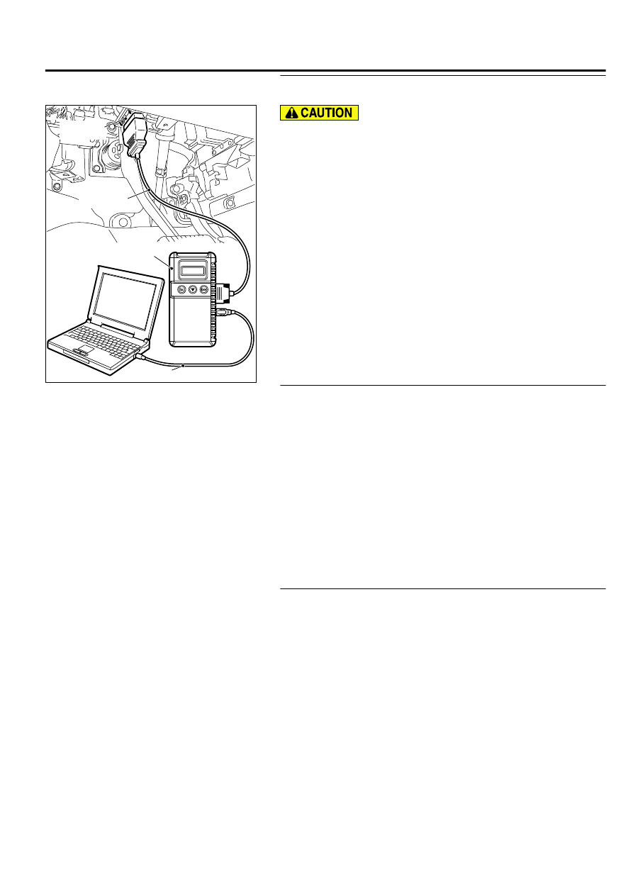
STEP 1. Using scan tool MB991958, read the diagnostic
trouble code (DTC).

ZC501967

AC404789

ZC5019680000

MB991824

MB991827

MB991910

Data link

connector

To prevent damage to scan tool MB991958, always turn the
ignition  switch  to  the  "LOCK"  (OFF)  position  before
connecting or disconnecting scan tool MB991958.

(1)

Connect scan tool MB991958 to the data link connector.

(2)

Turn the ignition switch to the "ON" position.

(3)

Read the DTC.

(4)

Turn the ignition switch to the "LOCK" (OFF) position.

Q:Is DTC P0451 set?

YES:

 Refer to DTC P0451 - Evaporative Emission Control

System Pressure Sensor Range/Performance P.13Ab-495.

NO:

 Go to Step 2.

STEP 2. Using scan tool MB991958, check data list item 52:
Fuel Tank Differential Pressure Sensor.

(1)

Turn the ignition switch to the "ON" position.

(2)

Remove the fuel cap.

(3)

Set scan tool MB991958 to the data reading mode for item
52, Fuel Tank Differential Pressure Sensor.

The fuel tank differential pressures should be 1,500 and
3,500 millivolts.

(4)

Turn the ignition switch to the "LOCK" (OFF) position.

Q:Is  the  fuel  tank  pressure  between  1,500  and  3,500

millivolts?

YES:

 Go to Step 3.

NO:

 Refer to DTC P0451 - Evaporative Emission Control

System Pressure Sensor Range/Performance P.13Ab-495.

STEP 3. Using scan tool MB991958, check actuator test item
10: Evaporative Emission Purge Solenoid.

(1)

Turn the ignition switch to the "ON" position.

(2)

Set scan tool MB991958 to the actuator test mode for item
10, Evaporative emission purge solenoid.

An operation sound should be heard and vibration should
be felt when the evaporative emission purge solenoid is
operated.

(3)

Turn the ignition switch to the "LOCK" (OFF) position.

Q:Is the solenoid operating properly?

YES:

 Go to Step 4.

NO:

 Replace the evaporative emission purge solenoid.

Then go to Step 6.

MULTIPORT INJECTION SYSTEM (MFI) <DIAGNOSIS>

13Ab-459

DIAGNOSTIC TROUBLE CODE PROCEDURES

STEP 4. Using scan tool MB991958, check actuator test item
15: Evaporative Emission Ventilation Solenoid.

(1)

Turn the ignition switch to the "ON" position.

(2)

Set scan tool MB991958 to the actuator test mode for item
15, Evaporative emission ventilation solenoid.

An operation sound should be heard and vibration should
be felt when the evaporative emission ventilation solenoid
is operated.

(3)

Turn the ignition switch to the "LOCK" (OFF) position.

Q:Is the solenoid operating properly?

YES:

 Repair or replace the vent hose and air filter. Then

go to Step 5.

NO:

 Replace the evaporative emission ventilation

solenoid. Then go to Step 6.

STEP 5. Check the trouble symptoms.

(1)

Carry out a test drive with the drive cycle pattern. Refer to
Diagnostic  Function  -  OBD-II  Drive  Cycle  -  Pattern  5  P.
13Ab-8.

(2)

Check the diagnostic trouble code (DTC).

Q:Is DTC P0441 set?

YES:

 Replace the ECM. When the ECM is replaced, register

the ID code. Refer to GROUP 42B, ID Code Registration
Judgment Table <Vehicles with KOS> P.42B-12or GROUP
42C, ID Code Registration Judgment Table <Vehicles with
WCM> P.42C-8. Then go to Step 6.

NO:

 It can be assumed that this malfunction is

intermittent. Refer to GROUP 00, How to Use
Troubleshooting/Inspection Service Points - How to Cope
with Intermittent Malfunctions P.00-15.

STEP 6. Test the OBD-II drive cycle.

(1)

Carry out a test drive with the drive cycle pattern. Refer to
Diagnostic  Function  -  OBD-II  Drive  Cycle  -  Pattern  5  P.
13Ab-8.

(2)

Read the diagnostic trouble code.

Q:Is DTC P0441 set?

YES:

 Retry the troubleshooting.

NO:

 The inspection is complete.

DTC P0442: Evaporative Emission Control System Leak Detected (Small Leak)

M11310100404USA0000010000

13Ab-460

MULTIPORT INJECTION SYSTEM (MFI) <DIAGNOSIS>

DIAGNOSTIC TROUBLE CODE PROCEDURES

ZK603429

K

A

B

C

D

E

F

G

H

I

J

AA00

Intake manifold

Fuel tank

Evaporative emission
ventilation solenoid

Check valve

Evaporative emission
purge solenoid

Evaporative  
emission canister

System diagram

Air filter

Vent pipe


ZK603430 AA00

Evaporative emission canister

ZK603611

Evaporative emission
purge solenoid

AA00

B-07 (B)

Connector: B-07


ZK603612 AA00

Evaporative emission
ventilation solenoid

Spare tire

B-116 (GR)

Connector: B-116


MULTIPORT INJECTION SYSTEM (MFI) <DIAGNOSIS>

13Ab-461

DIAGNOSTIC TROUBLE CODE PROCEDURES

TECHNICAL DESCRIPTION

The  ECM  monitors  the  Evaporative  Emission
(EVAP) System pressure.

The  ECM  controls  the  evaporative  emission
ventilation  solenoid.  It  closes  the  evaporative
emission  ventilation  solenoid  to  seal  the
evaporative emission canister side of the system.

The evaporative emission purge solenoid is opened
to  allow  manifold  vacuum  to  create  low  pressure
(vacuum) in the EVAP system.

When the EVAP system develops a vacuum of 2
kPa  (0.29  psi),  the  evaporative  emission  purge
solenoid is closed and the fuel system vacuum is
maintained at 2 kPa (0.29 psi).

The ECM determines whether there is a leak in the
EVAP system by monitoring the vacuum inside the
fuel tank.

The  test  is  stopped  when  fuel  vapor  pressure
exceeds predetermined limits.

DESCRIPTIONS OF MONITOR METHODS

Measure reverting pressure after depressurizing by
intake  manifold  negative  pressure  and  detect
malfunction if reverting pressure rises largely.

MONITOR EXECUTION

Once per driving cycle.

MONITOR EXECUTION CONDITIONS (OTHER
MONITOR AND SENSOR)

Other Monitor (There is no temporary DTC stored in
memory for the item monitored below)

Evaporative emission purge solenoid monitor

Evaporative emission purge system monitor

Fuel tank differential pressure sensor monitor

Evaporative emission ventilation solenoid monitor

Fuel level sensor monitor

Fuel temperature sensor monitor

Sensor (The sensors below are determined to be
normal)

Mass airflow sensor

Barometric pressure sensor

Intake air temperature sensor

Engine coolant temperature sensor

13Ab-462

MULTIPORT INJECTION SYSTEM (MFI) <DIAGNOSIS>

DIAGNOSTIC TROUBLE CODE PROCEDURES


Content   ..  314  315  316  317   ..